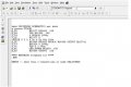
You would be better off cutting and pasting the code, rather than making us type it in from a screen shot.
Copy your spice code, and paste it here using the [C0DE] [/C0DE] delimiters.
OR
Click on 'Go Advanced', It is the button next to 'Post Quick Reply'.
On the top bar of the Advanced Editor there is a '#' button.
Click the '#' button then PASTE your code by pressing 'Ctrl-V' (Option-V on Macs)
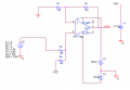
One of the mistakes is the to low resistance at the output.
The datasheet says it must be greater than 2K.
Change the 180 Ohms resistors (R1 and R2) to 10K each and see what happens.
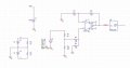
First off ... that is not the same circuit as the OP's listing.
Secondly, email is not the preferred medium for discussing these type problems, the forum is. Otherwise, no one else would benefit from the discussion.
this circuit is a voltage divider and for a wireless communication project (doing in college)
thank you bertus,JoeJester for your generous support...
we are now doing its in pspice for simulation ,let u show whats the current status of design (may suki tell ) after doing the above modification...
(imp:we are beginner in the field of pspice design so ..am expect generous and detailed explanation )
thanks
first of all, actually, I design it myself. I need to connect the circuit with MAX232A in pspice but it is not available in pspice, so i try to feed the pulses instead.and also, i fed the circuit with 3.7v which with the voltage summer, i expect the output to be the pulses of 3.7v to 4.2v. but no pulses at all being output.
sorry to post it here, because I don't know wherelese should I ask.
sorry, about the voltage summer, i found that it is useful when i want to use with the MAX232A, so in the modification, i've get rid of it. but still couldnt get any pulses as the result.
i need to work out with the frequency of 13.5Mhz because actually, I am building a break-down circuit of Near-Field Communication which is the transmitter part.
but when I try to design it in the pspice, the component of HA17741 is not the same with the one in the datasheet. what should i connect to the OS2 and OS1 node?

 Facebook
 Google
 GitHub
 Linkedin