Protection for the LF driver from DC out on the power amplifier.

Thread Starter

Fluminense

Joined Nov 6, 2015
5
Hello Guys,

Can somebody help me to build a circuit protection for my LF drivers from overheating due to DC out on my power amplifiers? Thanks in advance.

Fluminense
 

dendad

Joined Feb 20, 2016
4,641
You should not have DC outputting from an audio amp. If you do, it is a fault.
But, add a suitably rated Polyswitch in line with the LF driver as a simple protection.
No doubt there are other better solutions too, but a Polyswitch will help for now.
And a large value bipolar capacitor to block the DC.
But if there is DC, get the amp fixed.
 

Thread Starter

Fluminense

Joined Nov 6, 2015
5
Thanks for the reply, I agree what you've said that there's no DC output in a professional power amplifiers; however my amplifiers that drives LF drivers was not original one as you know their design were not the same performance as high quality amplifiers from CROWN, MARTIN AUDIO, LabGruppen and etc. I am just thinking to put additional inductor and bipolar capacitor in line with the driver. Appreciate your thoughts. Best regards...
 

#12

Joined Nov 30, 2010
18,224
There are just too many ways to do this starting from, "I wanna" with no information about power levels, brand, model, basic design of your amplifier, speaker size, etc. Narrow it down then ask again if you need something you can define.
 

Thread Starter

Fluminense

Joined Nov 6, 2015
5
There are just too many ways to do this starting from, "I wanna" with no information about power levels, brand, model, basic design of your amplifier, speaker size, etc. Narrow it down then ask again if you need something you can define.
The power amplifier I used was a clone from China class H design, 42 pairs power transistor on each channel 6 MOSFET 3 step supply voltages 0- 65-130-165vac secondary and torroidal transformer design; LF driver was also clone made to order 21" diameter with a 7" voice coil on it.
 

#12

Joined Nov 30, 2010
18,224
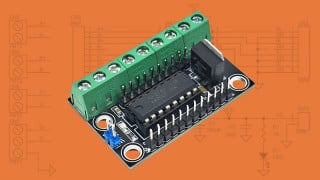
In order to do the math, it would be nice to know the wattage rating of the amplifier and the impedance of the speaker. That's how to get to volts and amps to size the components. I can easily imagine an RC filter to average the output voltage so that only the DC component would remain. The DC component has to be considered in both the positive and the negative polarity. Some voltage value must be decided, maybe like 1 volt persisting for one second, but the protector also has to respond to, "OMG I just blew out a dozen power transistors!":eek: You can't wait a whole second to respond to that. There is a lot of difference between a 50 watt living room amp and a thousand watts for a public performance. After deciding on the time constants and the urgency for speed, the comparator hits the panic button.

Oops. The real world just intruded. Gotta go.
 

crutschow

Joined Mar 14, 2008
38,689
If the DC output is always the same polarity, then you just need to add a series electrolytic capacitor.
The capacitor size should be greater than 1/(2Pi*Rs*fs) where Rs is the speaker impedance and fs is the lowest frequency of interest (typically 20Hz for a full range speaker).

Thus if the speaker is 8Ω and 20Hz is the -3dB frequency, then the capacitor value should be ≥1000μF.
Its voltage rating should be greater than the amp peak output

Make sure to observe the polarity of the capacitor as determined by the output offset voltage polarity.
 
Last edited:

Thread Starter

Fluminense

Joined Nov 6, 2015
5
If the DC output is always the same polarity, then you just need to add a series electrolytic capacitor.
The capacitor size should be greater than 1/(2Pi*Rs*fs) where Rs is the speaker impedance and fs is the lowest frequency of interest (typically 20Hz for a full range speaker).

Thus if the speaker is 8Ω and 20Hz is the -3dB frequency, then the capacitor value should be ≥1000μF.
Its voltage rating should be greater than the amp peak output

Make sure to observe the polarity of the capacitor as determined by the output offset voltage polarity.
Guys, thank you very much for the feedback. I'm still newbie and really appreciate your comments. With all your inputs regarding overheating the voice coil on the LF drivers, I strongly believed this could eliminate and rectify faults on my toys . Once again thank you so much for your help. All the best..
 

#12

Joined Nov 30, 2010
18,224
I think crutschow just embarrassed me. I was thinking about safety circuits I have seen in commercial amplifiers. They do this protect function for a few transistors and resistors that might cost a couple of dollars instead of $10 per channel in capacitors.

The capacitor method is excellent for blocking DC all the way up to catastrophic failure. I would think something that can stand the 136 volt maximum. There are a bunch here for $4 to $7 each:
https://www.mouser.com/Passive-Components/Capacitors/_/N-5g7r?P=1z0wrjwZ1yx4arh
I don't think you can buy this size in non-polarized but there is a way to use 2 of them to create a non-polarized equivalent.

I repaired an amplifier which had more than a volt of DC on the output because of a mismatch in the input transistors. (Bad from day one or because of some damage that happened over the course of several years?) The capacitor method will stop that measly volt or two from getting to the speakers, but I would not let that condition persist. You can either create a circuit to monitor DC offset or you can measure the DC output of each amplifier (at idle) from time to time. That's where I was headed.
 

crutschow

Joined Mar 14, 2008
38,689
I don't think you can buy this size in non-polarized but there is a way to use 2 of them to create a non-polarized equivalent.
Just connect them in series back-to-back.
They have enough leakage in the reverse direction to balance the charge between the two.
Of course each capacitor must be twice the desired total capacitance value.
 
Top