Protect Li-Ion overcharge/overdischarge protection board

Thread Starter

william.in.rs

Joined Jul 14, 2012
22
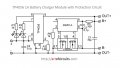
I was trying to replace pack of 3 NiMH batteries with single Li-Ion cell in my battery operated screwdriver. For ovecharge and overdischarge protection I was using small PCB with 4056E, DW01 and 8205A chips. Schematics of the board is attached. The problem is that the PCB blows up whenever I turn the screwdriver on.
Is there a problem in connecting inductive load (a motor) to the board? Could a reverse polarized diode between B- and OUT- do some help?
The motor is taking 1A to 2A depending on load so I think there is no need to replace 8205A (which is rated up to 5A) with stronger MOSFET. Am I right?
 

Attachments

Thread Starter

william.in.rs

Joined Jul 14, 2012
22
hi william,
Check this link
https://forum.allaboutcircuits.com/threads/tp4056-protection-board-manufacture-error.149502/
Also do a AAC Search for TP4056, there are a number of problems with some PCB's.
E
Eric, thank you for the information, I will check my next ordered boards when they arrive. But this is not the issue, for sure. All of my boards are working fine until I connect a motor to the OUT+ and OUT- terminals. The motor starts for a part of second killing the PCB.
 

dendad

Joined Feb 20, 2016
4,476
It is most likely the drill motor draws much more current that the protection FET can handle. Motors draw a lot of current when starting and under full load.
You may be able to use the board to drive a relay to supply the motor, or mod it to use a larger FET.
It looks like the max current is 6Amps. Can you measure the motor current when the motor is stalled?

What on the board dies? Is it the FET or a blown track or what?

And a reversed diode across the motor may help if it is popping the board from voltage spikes.
 

Thread Starter

william.in.rs

Joined Jul 14, 2012
22
You may be able to use the board to drive a relay to supply the motor, or mod it to use a larger FET.
The idea to use a relay is neat, thanks a lot.
It looks like the max current is 6Amps.
From the datasheet of DW01
Code:
In normal mode, the DW01-P continuously monitors the discharge current by sensing the voltage of
CS pin. If the voltage of CS pin exceeds the overcurrent protection voltage (VOIP) beyond the
overcurrent delay time (TOI1) period, the overcurrent protection circuit operates and discharging is
inhibited by turning off the discharge control MOSFET. The overcurrent condition returns to the normal
mode when the load is released or the impedance between BATT+ and BATT- is larger than 500kΩ.
The DW01-P provides two overcurrent detection levels (0.15V and 1.35V) with two overcurrent delay
time (TOI1 and TOI2) corresponding to each overcurrent detection level.
I can't figure out what current triggers overcurrent protection, but I think I've seen somewhere that it was 3A.
What on the board dies? Is it the FET or a blown track or what?
FETs are OK, looks like that DW01s have also survived. On most boards (I have destroyed quite few of them) charging controller chip (TP4056) died shorting VCC (pin 4) and BAT (pin 5) to the ground (pin 3).
I have only one board left and I need it to charge my other batteries. I think (with my poor elecronic knowledge) that DC motor must generate negative voltage and I have to protect the board from it. Protective diodes (which are built-in wih MOSFETS in 8205A) can't serve their purpose because they are counterpolarized and their common cathode stays open in the air (on not connected pins 1 and 8). I wonder whether a diode between OUT- (anode) and B- (cathode) would be enough to protect the board or should I put one between OUT- and OUT+ also.
 

Attachments

dendad

Joined Feb 20, 2016
4,476
A diode directly across the motor terminals, Cathode to +ve, Anode to -Ve. It will stop the high voltage spikes generated by the back EMF as the commutator switches.
Have you measured the motor current? Hook it up to a 3V or 4V supply and stop it turning. That will give max current. Don't hold it stopped for long though :)
I am interested to see if you get to the cause for sure as I use these boards too, but not to run a motor.
 

Thread Starter

william.in.rs

Joined Jul 14, 2012
22
A diode directly across the motor terminals, Cathode to +ve, Anode to -Ve. It will stop the high voltage spikes generated by the back EMF as the commutator switches.
Thanks!
Have you measured the motor current? Hook it up to a 3V or 4V supply and stop it turning. That will give max current. Don't hold it stopped for long though :)
It is about 6.5A.
I am interested to see if you get to the cause for sure as I use these boards too, but not to run a motor.
I am using it much too. First use with motor was about a year ago with table leftovers vacuum cleaner. Then I didn't realized that something is going wrong in connecting motor to the board, blew a couple of them and let the cleaner alone. Now I am waiting for new boards, when they arrive I will try to protect one with diode and post the result.
 
Top