Proper procedure for reducing ripple on DC power rail? (e.g. oscilloscope reading -> filter design)

ronv

Joined Nov 12, 2008
3,770
How would I calculate one of these for a 330KHz switcher instead?
Since I hate math I usually use LTSpice.

Can I also still use bulk capacitors like usual or does this need to be factored in differently?
If you are really serious about it a combination of electrolytic and ceramic might be the way to go. Ceramic are expensive for high values, but have good high frequency response while electrolytics are cheaper for high values but have poor high frequency response. You can't forget that even if the switcher is running at 330KHz it may have edges much higher.
[/QUOTE]
 

OBW0549

Joined Mar 2, 2015
3,565
How would I calculate one of these for a 330KHz switcher instead? Can I also still use bulk capacitors like usual or does this need to be factored in differently?
The component values aren't critical so you don't need to calculate if you don't want to: just use a BFI for the inductor and a BFC for each capacitor. I have a LM2577-based adjustable switching supply (52 kHz frequency) I occasionally use to power hobby stuff, and I filter its output with a two-stage L-C-L-C filter using 3 mH inductors and 100 μF capacitors. It's nice and quiet.

EDIT: just for kicks I made some measurements. Without the filter, the LM2577 switcher produced 250 millivolt peak-to-peak noise on its output, mostly in the form of narrow positive-going spikes. With the filter, the noise was below 400 μV p-p, all of it random "white" noise with no spikes visible. This was indistguishable from the background noise level with the switcher turned off and the CFL room lighting turned off.
 
Last edited:

Thread Starter

Mahonroy

Joined Oct 21, 2014
417
The component values aren't critical so you don't need to calculate if you don't want to: just use a BFI for the inductor and a BFC for each capacitor. I have a LM2577-based adjustable switching supply (52 kHz frequency) I occasionally use to power hobby stuff, and I filter its output with a two-stage L-C-L-C filter using 3 mH inductors and 100 μF capacitors. It's nice and quiet.

EDIT: just for kicks I made some measurements. Without the filter, the LM2577 switcher produced 250 millivolt peak-to-peak noise on its output, mostly in the form of narrow positive-going spikes. With the filter, the noise was below 400 μV p-p, all of it random "white" noise with no spikes visible. This was indistguishable from the background noise level with the switcher turned off and the CFL room lighting turned off.
Thats good to know thanks for that.

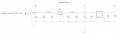
Here is what I came up with: (the datasheet for R-78E5.0-1.0 referenced 10uF input/output capacitors, so I chose the pi filter with 10uF cap and 33uH inductor):
Does this seem like a good solution?
clean_power_rail1.jpg
 

OBW0549

Joined Mar 2, 2015
3,565
That looks like it's worth a try, although I don't know that the filter ahead of your switching regulator (C55, L2 and C56) is really necessary. The second one is the critical one.
 
Top