 Facebook
 Google
 GitHub
 Linkedin
Hello Electronics Fans,
Today I have an LG, LD651EBL, 65 Pint Dehumidifier that has suddenly stopped working. Up until yesterday, it worked well although occasionally it gave me the 24 error indicating the pressure switch malfunctioned. However, a few minutes unplugged and it worked again after plugging it back in.
Now, however, it is a total failure. here are the symptoms....
1). The Display Panel does not respond at all when plugged in. Nothing, no lights, no beeps. (With the exception that there is one quick beep just as it's plugged in)...but then nothing else at all. So it's as if power is not getting to the power panel. Even though a few quick tests showed that it is)
What I have tried or checked.....
1). The fuse. On the Control board there is a small, glass Buss fuse (3.15, 250v) so I replaced it. No change
2). On the Display panel I checked the wires with a VOM and found 12.56v at two of them (but not the Red and Black wires)
3). I tried cleaning everything. no change.
4). Carefully inspected the Display board with a magnified, lighted loupe for indications of overheating, swollen CAPS, broken or burned traces etc. Nothing obvious.
So at this point I'm wondering if someone could give me some assistance in diagnosing the problem. Even if the compressor was bad or the freon had run out, (which I doubt), the Display Panel should still light up, so I'm thinking this is more of a power supply issue.
Any suggestions appreciated. My intent is to try to trace back the power from the cord to the Main Control board, then from there on to the Display Board.
Somewhere there is a voltage buck board or some other means of converting the 120VAC to DC 12v to the panel. That's where I'll probably explore next. This dehumidifier is over $200 new and does a great job so IF I can repair it for less than $50 I'd be thrilled.
Thanks for any help!
Photos below.....if more photos are needed, just say so;
Here is a photo of the front and back of the Display Board panel
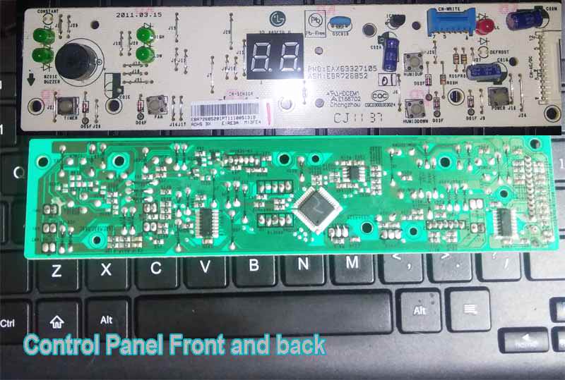
- The two larger rectangular IC chips are ULN2004L (high-voltage, high-current Darlington arrays )
- The small square chip in the center upper right is a 24CO1WP (appears to be an EEPROM of sorts) https://datasheet.octopart.com/M24C01-WDW6TP-STMicroelectronics-datasheet-17703652.pdf
- The larger, diagonally placed main IC chip is a TMP89FM42AUG (High-performance 8-bit microcontroller in compact package with On-chip oscillator and power-on reset circuit )
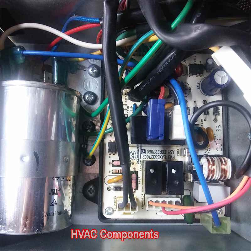
And here is a photo of the Main Control Board & HVAC control unit
Today I have an LG, LD651EBL, 65 Pint Dehumidifier that has suddenly stopped working. Up until yesterday, it worked well although occasionally it gave me the 24 error indicating the pressure switch malfunctioned. However, a few minutes unplugged and it worked again after plugging it back in.
Now, however, it is a total failure. here are the symptoms....
1). The Display Panel does not respond at all when plugged in. Nothing, no lights, no beeps. (With the exception that there is one quick beep just as it's plugged in)...but then nothing else at all. So it's as if power is not getting to the power panel. Even though a few quick tests showed that it is)
What I have tried or checked.....
1). The fuse. On the Control board there is a small, glass Buss fuse (3.15, 250v) so I replaced it. No change
2). On the Display panel I checked the wires with a VOM and found 12.56v at two of them (but not the Red and Black wires)
3). I tried cleaning everything. no change.
4). Carefully inspected the Display board with a magnified, lighted loupe for indications of overheating, swollen CAPS, broken or burned traces etc. Nothing obvious.
So at this point I'm wondering if someone could give me some assistance in diagnosing the problem. Even if the compressor was bad or the freon had run out, (which I doubt), the Display Panel should still light up, so I'm thinking this is more of a power supply issue.
Any suggestions appreciated. My intent is to try to trace back the power from the cord to the Main Control board, then from there on to the Display Board.
Somewhere there is a voltage buck board or some other means of converting the 120VAC to DC 12v to the panel. That's where I'll probably explore next. This dehumidifier is over $200 new and does a great job so IF I can repair it for less than $50 I'd be thrilled.
Thanks for any help!
Photos below.....if more photos are needed, just say so;
Here is a photo of the front and back of the Display Board panel
- The two larger rectangular IC chips are ULN2004L (high-voltage, high-current Darlington arrays )
- The small square chip in the center upper right is a 24CO1WP (appears to be an EEPROM of sorts) https://datasheet.octopart.com/M24C01-WDW6TP-STMicroelectronics-datasheet-17703652.pdf
- The larger, diagonally placed main IC chip is a TMP89FM42AUG (High-performance 8-bit microcontroller in compact package with On-chip oscillator and power-on reset circuit )
And here is a photo of the Main Control Board & HVAC control unit
Last edited:


