 Facebook
 Google
 GitHub
 Linkedin
Hi Guys
I have posted the meat of this elsewhere as I progressed with this little project. Bill Marsden suggested I post it here so it as a reference for anyone considering the use of a hot roller laminator for toner transfer.
Now this is fairly specific to the make/model of laminator I used but it could well be that it is fairly easy to adapt to other makes of laminator.
You will need;
A Texet LMA4-V laminator
An old clothes Iron
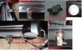
First up you will need to remove the 6 screws that hold the laminator case together. Once open you will see that the 'gubbings' are very simple. There is the motor which is bolted on the end of the transport. The switch, a small PCB that has the LED ready indicator on it.
The temperature control consists of 2 sealed factory set thermal switches. These are bi-metal types and they are screwed to the aluminium extrusion that contains the 2 heating elements (one for the upper roller and one for the lower roller. As well as containing the elements the extrusion shrouds the rollers.
Now at the opposite end of the extrusion there is a thermal fuse strapped to the metal. It is rated at 192 C and I managed to 'bugger it' before I came upon the idea of using the the thermostat of a clothes iron. It is on order to be replaced for safety!
First up undo the 2 screws of each thermal switch. These modules are wired in parallel so cut the pair of wires that realeases the pair.
Now dismantle your iron and hopefully you will find, as I did, that the thermostat of the iron is fixed to the hot plate by a single screw. Cut the wires then undo the bolt. The thermostat will come away easily. It is highly likely that one of the terminations may have a thermal fuse. The rating will be far higher than would be safe to ever run the laminator at so remove it.
Now firstly I used a junior hacksaw to cut a groove about 1/4 long that ran with the length of the bolt. I did this because the bolt diameter was a little bigger than the channel in the extrusion where the original thermal swithes screws had fitted. The groove helped the bolt to cut it's own thread into the softer aluminium. I did have to use a 2mm nut to take up some of the bolts length as it bottomed out in the channel before tightening up.
Thermal paste was also smeared on the mating faces to assist thermal transfer. The 2 wires from the original controls were then soldered to each of the terminals of the irons thermostat and heat shrink used where required to seal off bare ends. (This is not shown in my pictures) That is the mechanical side dealt with.
The only other thing I had to do was 'hack' a rather inelegant hole in the lower part of the case to take the height of the new thermostat. Again not shown I will be building a plastic surround to seal the metal parts of the thermostat away from careless fingers. The laminator itself will also need legs added as the thermostat protrudes downwards as well so the clearance is required. The original clothes Iron knob was retained as it has the temp settings on it.
The only other thing I did was remove the portion of the casing top above the molded slots where paper was supposed to be passed. In the photo where you can see the thermostat through the gap I will be fitting a plastic fillet to seal it off from accidental dropping of anything in the gap.
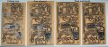
This mating of laminator and clothes iron may be fairly universal. The only thing will be the location of the new switch and any 'fettling' you may need to do to fix the thermal switch in place. Please note that as in my case the heating elements are sealed in the aluminium extrusion so if you need to drill and tap a hole for the fixing bolt don't blunder into the elements space. So far in the last 3 days since doing this mod I have made 8 PCB's. The stick down has been 99.9% - 100% perfect. A little trial and error was used to get an optimised quality of transfer. I am now heating the PCB by passing it 6 times through the unit and 7-8 times to transfer the toner pattern. My heat setting is a little over polyester.
The following pictures should demonstrate what the text has talked about. Please Please Please be aware that you are playing with an AC live circuit of whatever your locale voltage is. think safety safety safety!!!!!
regards
Fenris
I have posted the meat of this elsewhere as I progressed with this little project. Bill Marsden suggested I post it here so it as a reference for anyone considering the use of a hot roller laminator for toner transfer.
Now this is fairly specific to the make/model of laminator I used but it could well be that it is fairly easy to adapt to other makes of laminator.
You will need;
A Texet LMA4-V laminator
An old clothes Iron
First up you will need to remove the 6 screws that hold the laminator case together. Once open you will see that the 'gubbings' are very simple. There is the motor which is bolted on the end of the transport. The switch, a small PCB that has the LED ready indicator on it.
The temperature control consists of 2 sealed factory set thermal switches. These are bi-metal types and they are screwed to the aluminium extrusion that contains the 2 heating elements (one for the upper roller and one for the lower roller. As well as containing the elements the extrusion shrouds the rollers.
Now at the opposite end of the extrusion there is a thermal fuse strapped to the metal. It is rated at 192 C and I managed to 'bugger it' before I came upon the idea of using the the thermostat of a clothes iron. It is on order to be replaced for safety!
First up undo the 2 screws of each thermal switch. These modules are wired in parallel so cut the pair of wires that realeases the pair.
Now dismantle your iron and hopefully you will find, as I did, that the thermostat of the iron is fixed to the hot plate by a single screw. Cut the wires then undo the bolt. The thermostat will come away easily. It is highly likely that one of the terminations may have a thermal fuse. The rating will be far higher than would be safe to ever run the laminator at so remove it.
Now firstly I used a junior hacksaw to cut a groove about 1/4 long that ran with the length of the bolt. I did this because the bolt diameter was a little bigger than the channel in the extrusion where the original thermal swithes screws had fitted. The groove helped the bolt to cut it's own thread into the softer aluminium. I did have to use a 2mm nut to take up some of the bolts length as it bottomed out in the channel before tightening up.
Thermal paste was also smeared on the mating faces to assist thermal transfer. The 2 wires from the original controls were then soldered to each of the terminals of the irons thermostat and heat shrink used where required to seal off bare ends. (This is not shown in my pictures) That is the mechanical side dealt with.
The only other thing I had to do was 'hack' a rather inelegant hole in the lower part of the case to take the height of the new thermostat. Again not shown I will be building a plastic surround to seal the metal parts of the thermostat away from careless fingers. The laminator itself will also need legs added as the thermostat protrudes downwards as well so the clearance is required. The original clothes Iron knob was retained as it has the temp settings on it.
The only other thing I did was remove the portion of the casing top above the molded slots where paper was supposed to be passed. In the photo where you can see the thermostat through the gap I will be fitting a plastic fillet to seal it off from accidental dropping of anything in the gap.
This mating of laminator and clothes iron may be fairly universal. The only thing will be the location of the new switch and any 'fettling' you may need to do to fix the thermal switch in place. Please note that as in my case the heating elements are sealed in the aluminium extrusion so if you need to drill and tap a hole for the fixing bolt don't blunder into the elements space. So far in the last 3 days since doing this mod I have made 8 PCB's. The stick down has been 99.9% - 100% perfect. A little trial and error was used to get an optimised quality of transfer. I am now heating the PCB by passing it 6 times through the unit and 7-8 times to transfer the toner pattern. My heat setting is a little over polyester.
The following pictures should demonstrate what the text has talked about. Please Please Please be aware that you are playing with an AC live circuit of whatever your locale voltage is. think safety safety safety!!!!!
regards
Fenris
Attachments
-
 64.3 KB Views: 732
 -
 128.4 KB Views: 664
 -
 189.5 KB Views: 657
 I hope it is helpful to anyone considering trying the 'laminator' method. I would have tried months ago but it all seemed so complicated trying to 'convert' the beast.


