Programming and Debugging with PICkit3

Thread Starter

Chris.M

Joined Dec 9, 2009
11
Hello,

While programming a PIC chip with the PICkit3, should the components attached to the PIC pins be pulsed on and off erratically?

For example, I have an LED and a 20x4 LCD display connected to the PIC. During programming, the LED flashes erratically and similarly, the LCD cursor moves around erratically.

The target (PIC circuit) and the LCD are both powered with 5V while programming. There is a 4.7K resistor tieing MCLR to VDD, and all other pins from the PICkit3 are connected directly to the PIC.
The programming itself is successful and the circuit behaves correctly when running the PIC.

Is this behavior normal while programming using ICSP?


A second question is, while debugging, should the status LED on the PICkit3 turn red? Even with a simple LED flashing program, the status LED stays red until the chip is reset.


Kind regards,
Chris
 

spinnaker

Joined Oct 29, 2009
7,830
I have never experienced such problems.


Is the PIC and the LCD being powered externally with the 5V or are you trying to power it with the pickkit 3?


Does the circuit behave correctly with no pickit3?

Do you have bypass capacitors on the PIC and LCD VDD to ground?
 

thatoneguy

Joined Feb 19, 2009
6,359
If you have I/O on the PGC and PGD lines, they may flicker with the clock and data sent to the PIC during programming, power is also supplied to the PIC during programming. Vpp and Vdd pins are both powered, Gnd is grounded, and PGD and PGD are connected to the corresponding I/O on the PIC.

As long as you have resistors between the PIC and the load (say, an LED), so 5V is easily applied to the pin and doesn't sag due to the load, it will light both the LED and program the PIC. This is mainly for RB6( PGC) and RB7(PGD) on all mid-range devices.

The Status may be indicating that the circuit is being powered by the PIC Kit and not by the target board. That's not for certain, I get the lights mixed up between the 2s and 3s, I use the PIC Kit 2 a bit more often then the PIC Kit 3, but they are roughly the same for programming. I wish they'd have kept the logic and UART analyzer standalone program for the PIC Kit 3 though. Sorry for the sidetrack...
 
Last edited:

spinnaker

Joined Oct 29, 2009
7,830
If you have I/O on the PGC and PGD lines, they may flicker with the clock and data sent to the PIC during programming, power is also supplied to the PIC during programming. Vpp and Vdd pins are both powered, Gnd is grounded, and PGD and PGD are connected to the corresponding I/O on the PIC.

As long as you have resistors between the PIC and the load (say, an LED), so 5V is easily applied to the pin and doesn't sag due to the load, it will light both the LED and program the PIC. This is mainly for RB6( PGC) and RB7(PGD) on all mid-range devices.

The Status may be indicating that the circuit is being powered by the PIC Kit and not by the target board. That's not for certain, I get the lights mixed up between the 2s and 3s, I use the PIC Kit 2 a bit more often then the PIC Kit 3, but they are roughly the same for programming. I wish they'd have kept the logic and UART analyzer standalone program for the PIC Kit 3 though. Sorry for the sidetrack...

Good catch. I did not think the OP might be using pins that are connected to the programmer. I usually try avoiding using such pins because it can cause problems during debugging.
 

thatoneguy

Joined Feb 19, 2009
6,359
I use them, if there turns out to be an issue, I add a jumper to remove for those two pins for programming. No use wasting 2 I/O when you are starting with a low-pin count device. Especially true with 6 pin 10F200 (Size of SOT-23 transistor, but 6 pin package). They are often overlooked, but extremely handy for their size.

Look at AN656 on Microchip site, it explains how the ICSP works in great detail, including code on how to create an ICSP with a PIC.
 

Thread Starter

Chris.M

Joined Dec 9, 2009
11
I have never experienced such problems.


Is the PIC and the LCD being powered externally with the 5V or are you trying to power it with the pickkit 3?


Does the circuit behave correctly with no pickit3?

Do you have bypass capacitors on the PIC and LCD VDD to ground?
spinnaker, the PIC is powered externally, though the PIC and LCD are running off the same supply. Problem?

Yes the circuit behaves correctly after being programmed. With the PICkit3 connected or removed, and in both debug and release mode it runs correctly.

I have just placed a bypass capacitor on each of the PIC's VDD pins and one on the LCD VDD to ground, but these did not stop the LED flickering or the LCD behaving erratically.


If you have I/O on the PGC and PGD lines, they may flicker with the clock and data sent to the PIC during programming, power is also supplied to the PIC during programming. Vpp and Vdd pins are both powered, Gnd is grounded, and PGD and PGD are connected to the corresponding I/O on the PIC.

As long as you have resistors between the PIC and the load (say, an LED), so 5V is easily applied to the pin and doesn't sag due to the load, it will light both the LED and program the PIC. This is mainly for RB6( PGC) and RB7(PGD) on all mid-range devices.

The Status may be indicating that the circuit is being powered by the PIC Kit and not by the target board. That's not for certain, I get the lights mixed up between the 2s and 3s, I use the PIC Kit 2 a bit more often then the PIC Kit 3, but they are roughly the same for programming. I wish they'd have kept the logic and UART analyzer standalone program for the PIC Kit 3 though. Sorry for the sidetrack...
thatoneguy, there is no I/O on the PGC and PGD lines, both have dedicated pins just for programming.


It is only while the programming is taking place, that the LED flickers erratically and the LCD cursor moves erratically.

I will take a picture of the breadboard and attach the code shortly, in case I have missed something that I'm unaware of.
 

spinnaker

Joined Oct 29, 2009
7,830
It is only while the programming is taking place, that the LED flickers erratically and the LCD cursor moves erratically.

I will take a picture of the breadboard and attach the code shortly, in case I have missed something that I'm unaware of.
Now that you stated it again, I am pretty sure this is normal. As long as things turn to normal after you program the PIC.

If I recall correctly, I have seen my LCD flash when the PIC is being programed. Even when there is no power to the BL, I have seen it flicker.

I will confirm this for you tomorrow as I have a project sitting on my bench right now.
 

Thread Starter

Chris.M

Joined Dec 9, 2009
11
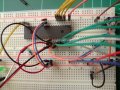
I have attached 2 images of the breadboard circuit, one is a zoom in to see more detail.

The LED is connected to pin RA6, and just stays on, although as described above, this flickers during programming.

The LCD data pins are connected to RC0 - RC7
The LCD R/W, RS and E pins are connected to RD0, RD1, RD2 respectively.

I'm using a PIC16F887. I have also attached the code.

Does anything look wrong with the circuit or the code, which may cause this erratic behaviour?
 

Attachments

Thread Starter

Chris.M

Joined Dec 9, 2009
11
Now that you stated it again, I am pretty sure this is normal. As long as things turn to normal after you program the PIC.

If I recall correctly, I have seen my LCD flash when the PIC is being programed. Even when there is no power to the BL, I have seen it flicker.

I will confirm this for you tomorrow as I have a project sitting on my bench right now.
Thanks spinnaker, I was hoping this might be the case and not my PICkit3 or circuit. We will know tomorrow after your confirmation.
 

spinnaker

Joined Oct 29, 2009
7,830
Thanks spinnaker, I was hoping this might be the case and not my PICkit3 or circuit. We will know tomorrow after your confirmation.
I just checked. My one project does not flash the LCD when programming. But I am almost certain that another project does.

On that project, the LCD power is controlled by the PIC. But that project is pretty much sealed up in a case now and I would rather not tear it apart.

My guess is those I/O pins are being reset.
 

Thread Starter

Chris.M

Joined Dec 9, 2009
11
I just checked. My one project does not flash the LCD when programming. But I am almost certain that another project does.

On that project, the LCD power is controlled by the PIC. But that project is pretty much sealed up in a case now and I would rather not tear it apart.

My guess is those I/O pins are being reset.
Thanks for checking spinnaker. So it looks like there isn't much to worry about.

Are there any LED's on you board that flicker really fast during programming?
 

spinnaker

Joined Oct 29, 2009
7,830
Thanks for checking spinnaker. So it looks like there isn't much to worry about.

Are there any LED's on you board that flicker really fast during programming?

On one project I am working on now, I do not see any but the PIC drives a demux and that drives the LEDs.
 

Thread Starter

Chris.M

Joined Dec 9, 2009
11
On one project I am working on now, I do not see any but the PIC drives a demux and that drives the LEDs.
If it's not too much of a hassle and you have the equipment setup, would you be able to connect an LED directly to a pin (with the appropriate resistor) and confirm if it flickers?
 

spinnaker

Joined Oct 29, 2009
7,830
If it's not too much of a hassle and you have the equipment setup, would you be able to connect an LED directly to a pin (with the appropriate resistor) and confirm if it flickers?

Easier done than said. :)


I have a demo board with a 18F45K20. I wrote a program that turns on all of the LEDs. Whenever I program the PIC all the lights go off then come back on. They might even flicker a tiny bit but not exactly sure. But for sure they go off and come back on.

I suspect that the PIC is being reset to it's default settings after it is programmed and the lights go off. Immediately, the program starts and the lights are tuned back on.
 

thatoneguy

Joined Feb 19, 2009
6,359
If it's not too much of a hassle and you have the equipment setup, would you be able to connect an LED directly to a pin (with the appropriate resistor) and confirm if it flickers?
Are your LEDs and LCDs connected to the PIC's Power rail? The programmer will pulse on for programming, again for reset, then verify. The ports may be in odd states if you have pull up resistors or are powering directly from the PIC.

On a big dev board, like the EasyPIC series, the LEDs do not flash during programming, but that may be a feature of the board.
 

Thread Starter

Chris.M

Joined Dec 9, 2009
11
Are your LEDs and LCDs connected to the PIC's Power rail? The programmer will pulse on for programming, again for reset, then verify. The ports may be in odd states if you have pull up resistors or are powering directly from the PIC.

On a big dev board, like the EasyPIC series, the LEDs do not flash during programming, but that may be a feature of the board.
Yes the LCD is powered from the same rail, and the LED is powered from the PIC pin.

It looks like the pulses applied to program, reset and verify as you have described may just be the cause for the pins being pulsed as well.

It looks like this can't be prevented then?
 

thatoneguy

Joined Feb 19, 2009
6,359
Yes the LCD is powered from the same rail, and the LED is powered from the PIC pin.

It looks like the pulses applied to program, reset and verify as you have described may just be the cause for the pins being pulsed as well.

It looks like this can't be prevented then?
It only happens for a very short time during initial programming, right?

You could make a board that has a PIC ZIF socket and ICSP header wired to the correct pins and program it off the board if that is required.
 

Thread Starter

Chris.M

Joined Dec 9, 2009
11
Easier done than said. :)


I have a demo board with a 18F45K20. I wrote a program that turns on all of the LEDs. Whenever I program the PIC all the lights go off then come back on. They might even flicker a tiny bit but not exactly sure. But for sure they go off and come back on.

I suspect that the PIC is being reset to it's default settings after it is programmed and the lights go off. Immediately, the program starts and the lights are tuned back on.
Thanks for testing that spinnaker. Now we know that the demo board does not display this behaviour, I can try determine if it's my PIC, PICkit3 or it's normal for this to occur.

It only happens for a very short time during initial programming, right?

You could make a board that has a PIC ZIF socket and ICSP header wired to the correct pins and program it off the board if that is required.
Yeah thats right thatoneguy. After programming, it works as expected.

Initially I was using a JDM serial programmer with a ZIF socket, but moved to a PICkit3 so I could do ICSP and not have to remove the PIC each time.

This is when I noticed the LED and LCD pins being pulsed during programming. So now I'm trying to determine if this is normal.

Perhaps the way to go is to use an EasyPIC6 Dev Board and do the prototyping on that.

It would be interesting to find out though, what that board has that prevents the pins from being pulsed during programming.

Sometimes RA2 or 3 will toggle during reprogramming.
blueroomelectronics, I'll keep this in mind, but my LED is on RA6 and the LCD on PORTC, so these pins are also being pulsed.
 

Thread Starter

Chris.M

Joined Dec 9, 2009
11
I just noticed my RA6 is CLKOUT so I moved the LED to pin RD3, but the flickering still occurs. So it's not just the pin I was originally using that flickers.
 
Top