Programmer cable and connector

Thread Starter

cmartinez

Joined Jan 17, 2007
8,218
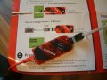
This is my PicIt 3. As you can see, I've attached a ribbon cable to it to make it easier to connect to my circuits. All of my circuits have a single file 5-pin 0.100" pitch standard header for this purpose.

74b9ae95-8e35-413a-b523-fb1ae1f3cdca.jpg

Ribbon cable connectors are all made for double file headers. So what I did is solder the individual cables in pairs as shown.

0acabe64-5801-4d1f-8d7d-2bf85dbe45b4.jpg

The problem is that such arrangement is a fragile one. And the cable's soldered joints tend to break over time with normal use.

Does anyone here knows a better way or technique to connect the programmer to a custom circuit?
 

MaxHeadRoom

Joined Jul 18, 2013
28,617
I prefer to use one method recommended by Microchip and that is the RJ-11 to ICSP adaptor from Microchip, on each board I have made where a program socket is needed, I use the RJ11 version.
 

Attachments

Thread Starter

cmartinez

Joined Jan 17, 2007
8,218
I prefer to use one method recommended by Microchip and that is the RJ-11 to ICSP adaptor from Microchip, on each board I have made where a program socket is needed, I use the RJ11 version.
Thanks for the suggestion, but most of the time I make good use of the header in my circuits, and connect peripherals to it. Using an RJ11 connector would interfere with that.
 

SamR

Joined Mar 19, 2019
5,031
The problem is that such arrangement is a fragile one. And the cable's soldered joints tend to break over time with normal use.
When I saw the picture and before I read the text I saw the potential problem. I would add some heat shrink or even 2 layers. Peel the ribbon cable by pairs back a bit to slide the tubing on. That would add a bit of mechanical strength. The second pair from the top is what I would be looking for. Tin the pins, twist and tin the cable pairs, then lay them on top of the pins and sweat them together. The more overlap the better. Even then my experience is that the weak spot is where the tinned and untinned cable meets which the shrink wrap will help with.
 

nsaspook

Joined Aug 27, 2009
13,080
Engineering a design that eliminates that solder failure point is the best long term solution IMO. The tall header ~20mm option moves the programmer above and clear of board components and provides a strong soldered attachment point though the PCB substrate. Design with a little extra enclosure edge clearance for ease of attachment.

PXL_20220624_181229161.jpg
 

MisterBill2

Joined Jan 23, 2018
18,167
Use a ten position double row connector with the strain relief but split the strands so you can use just the single side row of pins. That will give you the good strain relief and support.
 

Jon Chandler

Joined Jun 12, 2008
1,029
What a bunch of imaginative solutions.

You can buy 5 or 6 pin 0.1" pitch female headers on ebay or the Chinese sources. Find a header (male-to-male) header with extended pins to connect the one end of the female jumper to the PICkit.

Many PICkits come with such a cable.

Screenshot_20220624-120534_Edge.jpg
 

Thread Starter

cmartinez

Joined Jan 17, 2007
8,218
Solved it! ... instead of focusing on the cable, I should've focused on an adapter from the start.

And that's what I did. I assembled a simple ribbon cable with a couple of 2x5 header connectors at its ends (it annoys me to no end that I couldn't find the cable relief thingies that are supposed to be included with said connectors), and then I hacked a 90° header by cutting it to length, cutting the shorter row of pins, and then soldering its pairs of pins together. This way I don't have to worry about which row of the connector is attached to the PCB.

2f3c196f-a4f4-4c68-b764-bb7970fc7dd6.jpg 3b0ef883-fc8f-47e0-831e-646e0dd6e85f.jpg

ff655cff-61e6-4301-a84b-10021f78dadb.jpg 72bdb207-4af9-47d8-8043-51ad10be819f.jpg


f283a003-ac29-421e-b3d4-ed1124b5a291.jpg


The reason I used a 90° header is because its pins on the far side are much longer, and that allows it to be more easily inserted in the programmer without a hitch.
 
Last edited:

MisterBill2

Joined Jan 23, 2018
18,167
@Max, the other "advantage" of an RJ11 connector, like the RJ45, is that not only is it not field repairable, it also takes a special tool to install. Also, they are generally not re-usable.
THAT MATTERS A LOT in some situations.
 

MisterBill2

Joined Jan 23, 2018
18,167
One concern would be the quality of the crimp connection, especially if it requires a crimper not on hand. Soldering is an option but that is often hard on the insulation. and if only assortments are available that is a lot of stock to get the connectors required.
 
Top