Facebook
 Google
 GitHub
 Linkedin
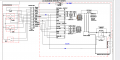
I have two brushless motor controllers (Kelly KLS-N line) that I want to control with a single input. This can be done easily with a dual pot, keeping the two controllers completely isolated. However, I would like to be able to use a microcontroller to interface with the controllers and for that purpose I am using a MCP4251 dual digital potentiometer to interface with the controller throttle input. (The throttle input is designed to be interfaced with a potentiometer wired to provide a voltage between 0 and 5 volts.) The Arduino is a 5V Pro Micro and powers the MCP4251.
I initially built a circuit with the three systems completely isolated (Arduino, controller A, and Controller B) naively thinking that the digital pots were isolated (I now know better). The result was the MCP4251 put out a intermediate value regardless of input and got quite hot.
Now I have provided a common ground for the Arduino and the controllers. The MCP4251 no longer gets hot, but only one of the outputs works at one time: both pots get 5V from their respective controllers but only one pot puts out the expected voltage, the other pot stays at 0v.
Another thing I noticed is that though the pots work fine (provide the same resistance) before the motor controllers are connected, once I connect the unpowered controllers to the circuit the output resistance drops significantly. (It's as if the 5kOhm output becomes a 3.5 kOhm output.) Once I power the controllers the above described problem kicks in.
Thoughts?
Is there a way to make this work or am I simply on the wrong track trying to use a digital pot for this purpose?