Problem with MAX038 Function Generator IC

Status
Not open for further replies.

Thread Starter

ericfellip

Joined May 10, 2013
10
Hello all!
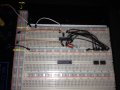
I would like some help trying to figure out what I am doing wrong with my circuit. I have some audio projects I want to do to start a music equipment company, and I need a function generator to test my circuits. I saw this MAX038 as an appealing alternative since it doesn't seem to be really hard to make the generator (although I'm aware that this is an obsolete component). I am trying to test it with a breadboard to see if everything is according to what I would expect before designing the PCB, and this is where I have a problem.

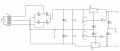
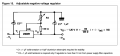
I have a homemade adjustable (+15V)-0-(-15V) power supply I designed myself using LM317 and LM337 (I am using the high current models) which can deliver 1A of current if necessary, which I think is more than enough to power the IC. The circuit I am trying to build is the one contained in the component datasheet (Figure 2, Page 11, link below). The main problem is that, when connecting some pins to GND (about 5 pins), the negative power supply rail starts to oscillate (I am powering it +5v and -5v) around those -5V, with the positive power supply staying stable. Not only that, the IC starts to heat up like a CPU without a cooler, and gets to burning point in about 4 seconds.

This is what I can't figure out, because the schematic is on the datasheet, and I don't think I am connecting it wrong (I am studying electronics in a trade school and I did 1,5 years of a 2-year course, so I don't consider myself a total ignorant wiring circuits), but if I am, would anybody with more experience help me? Is the problem in the wiring of the circuit or in my power supply? Sorry about opening a topic on an obsolete component, but I searched the forum and nobody seemed to have the same problem as myself.

Thanks in advance for your help,

Eric.


Links:
MAX038 Datasheet http://datasheets.maximintegrated.com/en/ds/MAX038.pdf
 

Lestraveled

Joined May 19, 2014
1,946
Since you are using a proven schematic, the problem must be in the construction/layout of the circuit. Please post some clear pictures of your build.
 

Thread Starter

ericfellip

Joined May 10, 2013
10
I will arrange some pictures of the breadboard, I'll try to make the wiring as understandable as possible. One major doubt of mine is if my power supply is not able to withstand the current demand and is going crazy because of it, could that be it?
 

Thread Starter

ericfellip

Joined May 10, 2013
10
Here are two photos of the breadboard, the only things omitted are the frequency selection potentiometer (between pins 1 and 10) and the supply rails capacitors. The orange cables are the +V connections, the white cables are the -V connections, and the black cables are the GND connections. The pins that should be directly connected to GND (since according to the datasheet they are not internally connected) are pins 2, 3, 6, 7, 9, 11, 12, 13, 15 and 18, with 3 being the only one missing the connection in these photographs.


The circuit schematic is the one in my power supply, I didn't connect output capacitors in it but "compensated" that in a way by connecting two 2200uF capacitors before the adjustable regulators. Maybe the power supply is failing somehow?

Thanks for all the help,

Eric.
 

Attachments

Lestraveled

Joined May 19, 2014
1,946
You are missing the decoupling capacitors at the MAX038 and on the LM317/337. very Big NO NO.
Look at the schematic of the MAX038. It shows 1uf caps on the +5 and -5 power. You need these. They must be located at the chip.

Look at the data sheets for the regulators. They also have capacitors at the output. They have to be right at the output of the regulator.

Also, your hookup leads are too long. The MAX038 is a 20MHz chip. It needs good grounding and short leads.
 

Thread Starter

ericfellip

Joined May 10, 2013
10
Ok, will do that and get back to you. But you think the filter capacitors alone are the cause of the excessive heating on the device? (only time I ever saw components heat like that was when they were shorted out, which seems to be the case in some way I believe).


Thanks for everything,

Eric.
 

Lestraveled

Joined May 19, 2014
1,946
Even though you may only use it at audio frequencies, it is still a 20 MHz part. This means layout is very critical. If you had used a 8038, a 100KHz part, layout would be far less sensitive.
 

Thread Starter

ericfellip

Joined May 10, 2013
10
One more thing: Do you think that things will improve if I put the decoupling capacitors for the LM3x7 on the breadboard while prototyping? Or I really need them on the PCB as close to the regulators as possible?

Thanks,

Eric.
 

Thread Starter

ericfellip

Joined May 10, 2013
10
You are right there, while the voltage was oscillating on the power supply I was getting to 9, maybe 12v when increasing, but oscillating too fast I believe to do any damage. Will make a new PCB for the power supply and I will get back to you.

Another question: The output capacitors on the LM3x7 datasheets are rated at 1uF. That value was selected because with that capacitance it can filter a particular frequency on the surge peaks, or it was simply for a basic filtering purpose? If the latter, would there be any problem if I increase it?


Thanks,

Eric.
 

Lestraveled

Joined May 19, 2014
1,946
Put them right at the regulator. Most data sheets for the LM317 have at least a poor description of decoupling requirements. If you want to use a bigger cap, put a .1uF in parallel with it.
 

crutschow

Joined Mar 14, 2008
34,280
..........................
I didn't connect output capacitors in it but "compensated" that in a way by connecting two 2200uF capacitors before the adjustable regulators.
.........................
Input capacitors in no way "compensate" for not having output capacitors. Why would you think they would and why would they show them on the output of the regulator in the data sheet if they weren't needed? :confused:
 

atferrari

Joined Jan 6, 2004
4,764
One more thing: Do you think that things will improve if I put the decoupling capacitors for the LM3x7 on the breadboard while prototyping? Or I really need them on the PCB as close to the regulators as possible?

Thanks,

Eric.
Eric,

Solder them to the pins and forget that part of the problem.
 

Thread Starter

ericfellip

Joined May 10, 2013
10
First, I want to thank all of you that helped me, I appreciate it.

I designed the power supply again (image 01 below), introducing two 100nF mylar film capacitors on the input to bypass high-frequency AC, two 10uF electrolytic capacitors in parallel with the voltage adjustment potentiometer, and two 10uF tantalum capacitors on the output.

On the breadboard I inserted all the capacitors as the datasheet demanded, and happily turned on the power supply. Sadly, no luck.

The -V rail oscillated again and the chip was burning hot like a stone in the desert. The good part at least was that the voltage of the oscillations never passed the 3V mark, so it didn't damage the terminals.

What may I look for next?

Thanks for the help,


Eric.
 

Attachments

Lestraveled

Joined May 19, 2014
1,946
First, do not use your expensive MAX038 as a test load for your power supply. Use resistors that will draw about the same current.

Second, the pot, RV2, should not connect to U2- pin 3.

Work the bugs out of your power supply before you connect it to other devices.
 

Thread Starter

ericfellip

Joined May 10, 2013
10
Hello Bertus,

About those remarks, what would differ in functionality with the values you posted and with the ones I'm currently using? I can't seem to figure it out, only that the path to the adjustment pin would be far less resistive to current if it increased somehow.


Lestraveled:

The RV2 connecting to the U2 pin-3 was an error that happened when I was reviewing the schematic to post here because it was too messy, but on the original design they are not connected. The supply is fine now I believe, the only review should be the remarks Bertus made. Also, about the MAX038, according to the datasheet, the +V operating current should be typically 35mA and the -V current 45mA, but I don't have a multimeter with DC current measuring, only one of those clamp multimeters that only measure AC. Despite that, I don't trust the datasheet very much anymore :p


Thanks all,

Eric.
 

bertus

Joined Apr 5, 2008
22,270
Hello,

The 120 Ohms resistor is taken from the datasheet.
Here is the schematic for the LM337:


The lower value for the R1 is for better stability of the regulation.
The voltage will be less dependend on the Iadj.

Bertus
 

Attachments

Status
Not open for further replies.
Top