Problem with intelligent traffic light

Thread Starter

AhmedHelmy

Joined Dec 16, 2017
8
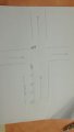
I designed a traffic light for two cross roads but there is another request in this project where I will connect sensors .
If the second road carrying a red signal was heavy traffic more than a kilometer makes the signal green and the first road that carries a green signal becomes a red signal.
How can I install the IR sensor and connect it to the traffic signals so that this congestion occurs and makes a switch between the signals ?
*I sent my project in the attachments and the idea of installing sensors on the road*
 

Attachments

absf

Joined Dec 29, 2010
1,968
If the second road carrying a red signal was heavy traffic more than a kilometer makes the signal green and the first road that carries a green signal becomes a red signal.
Can you rephrase the above sentence? Make what you want clearer..
What do you mean by "more than a km makes the signal green"?

How can I install the IR sensor and connect it to the traffic signals so that this congestion occurs and makes a switch between the signals ?
Not sure what you want...
Do you want to know how to install the IR sensor, or how to make use of the signal coming from the IR sensor when the condition is met?

BTW, do you have the schematic in proteus format so I dont have to do it again...

Allen
 

absf

Joined Dec 29, 2010
1,968
Why do you need 4 sensor on the NS traffic but none on the EW traffic?

Is the timer pulasing at 1 Hz with a duty cycle of 90%? Assuming 5.2K, 640 ohm 220uF.

Allen
 

absf

Joined Dec 29, 2010
1,968
This thread looks like Home Work to me, so I doubt The TS was allowed to interface to such a sophisticated device.:D;)

Allen
 

Thread Starter

AhmedHelmy

Joined Dec 16, 2017
8
Can you rephrase the above sentence? Make what you want clearer..
What do you mean by "more than a km makes the signal green"?


Not sure what you want...
Do you want to know how to install the IR sensor, or how to make use of the signal coming from the IR sensor when the condition is met?

BTW, do you have the schematic in proteus format so I dont have to do it again...

Allen
In my project, I'm supposed to connect 4 IR sensors to cover a distance of 1 KM. And supposedly, when the 4 of them are cut in a red light, the two traffic lights will swap so that the traffic with red light will become green and the traffic with green will become red to decrease the volume of traffic in this intersection.
Also, when an emergency car is passing, with the use of a push button as an indication, the counters in both traffic lights will freeze on whatever number it's on, and the lights will swap. So that the intersection with an emergency car will be green and the other one will be red until the emergency car passes, then everything will be back to normal and the counters will continue from where they stopped the count.
 

Attachments

absf

Joined Dec 29, 2010
1,968
S-TRAFFIC_1.PNG
I ran it on proteus and saw that it was quite well designed.

TL1 is always 5 seconds behind TL2. The sequence goes something like this:

Code:
   TL1                  TL2
1. Red 30 s          Green 25 s
2. Red 5 s            Amber 5 s
3. Amber 5 s         Red 30 s
4. Green 30 s        Green 25 s ...... loop back to 2.
So each TL1/TL2 runs their own timing sequence with their own set of chips. Only thing they share is the 555 clock pulses.

With the introduction of the interrupt signal from IR sensors, You have to overwrite the TL1 sequence as well as the TL2 sequence will be affected.

To add the interrupt signal is easy. Since there are 4 sensors, I'd use a 4-input AND gate assuming the sensor outputs are active high. Since only CMOS got 4-input AND, you may use 7413 or 7440 together with a NOT gate 7404 to make the AND gate needed.

Try using the signal on TL1 first to make the RED turn to AMBER to see if that work first. Later then figure out how to apply the same signal to TL2 so they would synchronize with each other.

Allen
 

absf

Joined Dec 29, 2010
1,968
I have tried to use the sensor signal to trigger a 555 one shot to generate a short negative pulse. This pulse steps the 4017 so it turns from Red to Green. It works but the counter is still counting ignoring the change in lights.

So I think another way is to use a second 555 to generate 10 Hz clock to step the counters when sensor signal is detected on TL1. It should revert back to the 1 Hz clock when the Green turn to Amber in TL2.

But, still the easiest way is to use a PIC or AVR or even an Arduino to do this. I figure it would need 11 pins for 4 digit display, 4 pin for the traffic lights and 1-2 pins for the sensor signals.

Allen
 
Last edited:

absf

Joined Dec 29, 2010
1,968
Here's what I did but doesnt work as I wanted.:D:(
Others may chip in to give you more clues.

TRAFFIC_MOD.PNG

Items in blue rect are added circuits.

Allen
 

panic mode

Joined Oct 10, 2011
2,715
it is a project not a homework
really? no offense but i call that baloney... :)

one thing is to do an academic study (learning about logic), another is to make a functional product and put it to commercial use.

in this case there are several issues worth mentioning:

traffic light is not something that works 15 minutes in a controlled environment. it is something that should work for many years in various conditions and still work reliably. this requires some careful design considerations. and this design fails in soooo many ways.

it can literally KILL PEOPLE. there is absolutely NOTHING here that ensures that two roads can never get GREEN LIGHT AT THE SAME TIME!!! the only thing that is common to both TL1 and TL2 is clock... no interlocks. i call that serious design flaw and direct violation of no nonsense rule.

i don't see any reset logic, counter states would be random after brownout or power outage.

one thing you don't want to do is promote road rage and violence. i would be seriously ticked off to sit every day in a 0.1km long backup artificially caused by some red traffic light. dealing with this as a problem when backup is entire 1km log is going to have lynch mob looking for blood...

this design is using half a century old technology and using it incorrectly. it lacks any flexibility, and it uses more than a dozen of ICs when one could do the job (and do it much better).
mixing TTL and CMOS logic, not only they have different logic levels but there are limitations to interfacing one with another.

TTL requires precise supply voltage, i don't see any regulators
i don't see any boot strap capacitors, any current limiting resistors for the displays
 
Last edited:

absf

Joined Dec 29, 2010
1,968
really? no offense but i call that baloney... :)
Just learned a new word 'baloney':D

it can literally KILL PEOPLE. there is absolutely NOTHING here that ensures that two roads can never get GREEN LIGHT AT THE SAME TIME!!! the only thing that is common to both TL1 and TL2 is clock... no interlocks. i call that serious design flaw and direct violation of no nonsense rule.
That's true. If one of the 74192 refuses to count then the whole system would be in a mess.

one thing you don't want to do is promote road rage and violence. i would be seriously ticked off to sit every day in a 0.1km long backup artificially caused by some red traffic light. dealing with this as a problem when backup is entire 1km log is going to have lynch mob looking for blood...
I totally agree. One KM is too long a queue for people to wait. May be 100M is reasobable.

Reminds me of the waiting at the ferry during New Year holidays. That was before our govt had the bridge built. Lots of people became impatient and started to jump queue and began to create commotions at the ferry entry.

this design is using half a century old technology and using it incorrectly. it lacks any flexibility, and it uses more than a dozen of ICs when one could do the job (and do it much better).
mixing TTL and CMOS logic, not only they have different logic levels but there are limitations to interfacing one with another.
But if he use 74HCxxx logic chips it would be fine.

Thats why I believe it is either a 'school assignment' or 'Homework' or just a 'Hobby Project' for learning Electronics.

TTL requires precise supply voltage, i don't see any regulators
i don't see any boot strap capacitors, any current limiting resistors for the displays
May be this is just a ' hobby project in simulator'. No actual PCB or product was made.

Allen
 
Top