Facebook
 Google
 GitHub
 Linkedin
I built this I/R sensor circuit a while back. I had everything working perfectly till I had a tragic accident with my CNC machine (it was to be the RPM sensor for the machine). So I had to rebuild the thing from scratch.
Now I am not getting a transition at all on pin on of the LM2903.
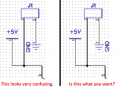
My supply is +5V. I have verified supply is at pin 8 of the op amp
Pin 1 sits at a solid 0.975V no change reflecting or not reflecting.
Pin 3 is at 0.495 volts.
The strangest thing is on Pin 2. Not reflecting it is at around 4 volts but then I see these periodic transitions to around a few milli volts. Sometimes it stays there for less than a second. Other times it stays there for several seconds.
I have turned off any potential source of I/R like my florescent light.
Reflected pin 2 is just a few milli volts.
I was able to capture one transition right in the middle of the transition and included it below.
If the op amp is pulled out of the circuit then pin 2 (of the socket) stays at just a little over 3V not reflected and goes to just a few milli volts when it is reflected.
I have tried 2-3 opamps all with the same result.
This is very frustrating since I already had the thing working.
My only difference between what I have now and what I had working is I am fairly certain R1 used to be a 20k. I don't know why I did it but I salvaged the old board for parts. It was stupid. Somehow I thought it would be easier swapping out parts. I should have left everything intact.
The other change was R6 was originally left out of the design. After realizing my mistake I simply soldered a 10K from pin 1 of J1 to pin 1 of J2. I then updated the pcb design in the event I was going to make more boards. But I can't see how that could cause an issue.
But could too high of a value for R1 cause those strange oscillations?


Now I am not getting a transition at all on pin on of the LM2903.
My supply is +5V. I have verified supply is at pin 8 of the op amp
Pin 1 sits at a solid 0.975V no change reflecting or not reflecting.
Pin 3 is at 0.495 volts.
The strangest thing is on Pin 2. Not reflecting it is at around 4 volts but then I see these periodic transitions to around a few milli volts. Sometimes it stays there for less than a second. Other times it stays there for several seconds.
I have turned off any potential source of I/R like my florescent light.
Reflected pin 2 is just a few milli volts.
I was able to capture one transition right in the middle of the transition and included it below.
If the op amp is pulled out of the circuit then pin 2 (of the socket) stays at just a little over 3V not reflected and goes to just a few milli volts when it is reflected.
I have tried 2-3 opamps all with the same result.
This is very frustrating since I already had the thing working.
My only difference between what I have now and what I had working is I am fairly certain R1 used to be a 20k. I don't know why I did it but I salvaged the old board for parts. It was stupid. Somehow I thought it would be easier swapping out parts. I should have left everything intact.
The other change was R6 was originally left out of the design. After realizing my mistake I simply soldered a 10K from pin 1 of J1 to pin 1 of J2. I then updated the pcb design in the event I was going to make more boards. But I can't see how that could cause an issue.
But could too high of a value for R1 cause those strange oscillations?
")