Problem with h-bridge inverter.

Thread Starter

rocon123

Joined Jun 26, 2015
27
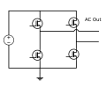
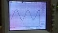
I am converting DC voltage to AC via H-bridge inverter. I am using bipolar SPWM signals to control IGBT switches of H-bridge. When i connect 470ohm load to output terminal it retains sine shape. when i decrease load to 70ohm, sine wave distorts at zero crossing. how to avoid this? attached figure of both results.(1)with 470ohm as load.(2)with 70ohm as load.
 

Attachments

mcasale

Joined Jul 18, 2011
210
From your original question, it looks like the H-bridge MOSFETs may not be driven hard enough to get them into saturation quickly.

It could also be that your power supply is dropping out a bit. What is its current rating? Have you bypassed it right at the H-bridge?

It's important to show how the MOSFET gates are driven. Otherwise, this is all guess work.
 

Thread Starter

rocon123

Joined Jun 26, 2015
27
From your original question, it looks like the H-bridge MOSFETs may not be driven hard enough to get them into saturation quickly.

It could also be that your power supply is dropping out a bit. What is its current rating? Have you bypassed it right at the H-bridge?

It's important to show how the MOSFET gates are driven. Otherwise, this is all guess work.
attached datasheets of driver and IGBT. At gate terminal i am giving 15V DC for switching it on.
 

Attachments

mcasale

Joined Jul 18, 2011
210
Here's 2 things that come to mind:

1. It looks like they use an external current sense resistor that goes into a comparator. I'm guessing this is used to limit the maximum current. Make sure you set this right for your load or it will [probably] turn off the drivers.

2. If you can, look at the signals driving the IGBTs to ensure they are not both on at the same time. That will cause a "short" to ground, limited only by that current sense resistor. Be careful that the capacitance of your scope probe does not interfere with the actual operation.

And a question: what is the current capacity of your "high voltage supply"? Put your scope probe on it near the power IGBTs and see if it's dropping out at the switching points.
 

Thread Starter

rocon123

Joined Jun 26, 2015
27
Here's 2 things that come to mind:

1. It looks like they use an external current sense resistor that goes into a comparator. I'm guessing this is used to limit the maximum current. Make sure you set this right for your load or it will [probably] turn off the drivers.

2. If you can, look at the signals driving the IGBTs to ensure they are not both on at the same time. That will cause a "short" to ground, limited only by that current sense resistor. Be careful that the capacitance of your scope probe does not interfere with the actual operation.

And a question: what is the current capacity of your "high voltage supply"? Put your scope probe on it near the power IGBTs and see if it's dropping out at the switching points.
1.drivers remain on, that is why i am getting a wave.(distorted even)
2.PWms' are exact complementary with deadband.

current capacity of power supply is 2A. if we look at IGBT datasheet, the current rating is very high for it. so no need to check it.
 

Alec_t

Joined Sep 17, 2013
14,313
sine wave distorts at zero crossing. how to avoid this?
I believe the distortion is due to the voltage drop across the semiconductor junctions within the IGBT. That drop is current-dependent, so produces a more noticeable effect at higher currents (i.e. when the bridge load resistance is decreased). I don't see how you can eliminate it.
 
Top