 Facebook
 Google
 GitHub
 Linkedin
Hi, I have been working on a tesla coil design, and it involves a half bridge inverter. My goal is to use a LC as the load to both act as the primary coil of the tesla coil and also achieve soft switching at the same time, but the simulation result shows the power dissapation is too high with LC as the load.
However when I use a resistor as the load instead, I get a square wave(which I believe is the ideal output) but it has some really wierd charachteristics, as you can see from the picture below, the positive voltage is very high in contrast to the low negative voltage. Also I find that by increasing the load resistance the negative voltage increases and the positive decreases, hope this clue helps.

I believe the positive and negative voltage are each supplied by the two 1m capacitors, I find that their voltages match(as seen from the picture below), the red line is C4(name is in the circuit) and the green line is C3.

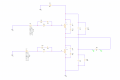
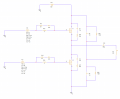
Below is the circuit of the half bridge, input voltage is 320V with a switching frequency of around 154Hz, also I'm using two IGBTs as the switch(AFGB40T65RQDN), the LC is tuned to the same frequency as the half bridge.
(the square wave I got was just swapping the LC with a 5k resistor)

Can anyone explain what causes the high positive and low negative when I use the resistor as the load, and what I can do to make the positive and negative voltage be the same without increasing the load resistance.
Also what are some methods I can use to get rid of the high spikes.
Lastly how can I use the LC as the load without creating excessive heat that will destroy the circuit.
Thanks in advanced!
However when I use a resistor as the load instead, I get a square wave(which I believe is the ideal output) but it has some really wierd charachteristics, as you can see from the picture below, the positive voltage is very high in contrast to the low negative voltage. Also I find that by increasing the load resistance the negative voltage increases and the positive decreases, hope this clue helps.
I believe the positive and negative voltage are each supplied by the two 1m capacitors, I find that their voltages match(as seen from the picture below), the red line is C4(name is in the circuit) and the green line is C3.
Below is the circuit of the half bridge, input voltage is 320V with a switching frequency of around 154Hz, also I'm using two IGBTs as the switch(AFGB40T65RQDN), the LC is tuned to the same frequency as the half bridge.
(the square wave I got was just swapping the LC with a 5k resistor)
Can anyone explain what causes the high positive and low negative when I use the resistor as the load, and what I can do to make the positive and negative voltage be the same without increasing the load resistance.
Also what are some methods I can use to get rid of the high spikes.
Lastly how can I use the LC as the load without creating excessive heat that will destroy the circuit.
Thanks in advanced!
Attachments
-
 27.6 KB Views: 3
 -
 25.9 KB Views: 3


