Facebook
 Google
 GitHub
 Linkedin
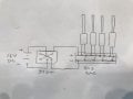
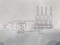
I'm trying to wire 4 12V electric linear actuators in parallel using a DPDT rocker switch. When I wire them directly to my power supply they work fine.
When I try wiring in the switch they do not. I have two switches and have tried them both so doubtful it's a faulty switch. Here are the details.
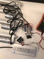
12V 12.5 amp 150W DC power supply
4 12V 3 amp linear actuators wired in parallel
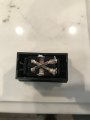
12V 30 amp DPDT rocker switch
Any help would be greatly appreciated.
When I try wiring in the switch they do not. I have two switches and have tried them both so doubtful it's a faulty switch. Here are the details.
12V 12.5 amp 150W DC power supply
4 12V 3 amp linear actuators wired in parallel
12V 30 amp DPDT rocker switch
Any help would be greatly appreciated.