Problem with DIY high voltage regulated Power Supply

Thread Starter

e00rica

Joined Jan 11, 2021
3
Hi,
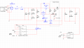
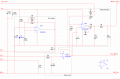
I am writing this post in the hope that someone can help me to solve this problems. I found this project on the internet and since I need this kind of power supply, I decided to build a similar one.
I basically have two problems with the circuit: One is that when I have regulated the voltage down to a few millivolts and let it stay there for a few minutes and try to raise the voltage again, the transistor (Q7) smokes. Problem number two is that R8 resistor gets too hot when Q1 is leading. I resolve this by placing a 1 Kohm effect resistor between Q1-Source and earth but I'm not sure it's the right thing to do.
Thank you!
Here is the youtube-link for the project I found on internet:
by Smith Kerona
 

Attachments

AnalogKid

Joined Aug 1, 2013
10,587
What is the maximum output current you want at 300 V, 150 V, 5 V, and 0.1 V?

Your basic problem is excessive power dissipation in your components. There are three equations for this, all variations of the same theme:

P = E x I

P - E^2 / R (Watt's Law)

P = I^2 x R (Joule's Law)

If you pick an arbitrary output condition, such as 10 V at 1 A, you can work backwards through the components and see the power dissipated in each.

Linear power supplies are inefficient by definition, and that means they produce a lot of heat. If you have 10 V at 1 A at the output, then 300 W ((310 V-10) V x 1A) is being dissipated somewhere. That's a lot. You'll need fans.

AND - what is the purpose of R12. At 1 A output current, the voltage drop (Ohm's Law) is 100 V, reducing the maximum output voltage to 200 V, and the power dissipation is 100 W.

ak
 
Last edited:

tindel

Joined Sep 16, 2012
933
This is not a trivial power supply to develop. I'll suggest three edits.
1)
Your Q2 transistor is smoking because your bandwidth is too high. i=C*dv/dt. If you assign it to 200V and it gets to 200V too quickly, you have very large currents charging your output caps and taking you out of your safe operating area of the transistor. You need to add some slew rate control. I'd suggest readding the opamp your removed from the original circuit and filtering its input signal to have a time constant of ~1s (or more) to limit the speed at which the output voltage ramps up or down after an adjustment has been made.

2)
1684603376884.png
Adding the Rsense and Q2 in this image will provide a rough current limit - better than R12. More info can be found here: Current limiting - Wikipedia. This will also help with #1.

3)
The video describes that mosfet as having a large input capacitance - and he's right! I'd pre-bias the gate so that it's always charged up. Basically, add a resistor on the trim pot so the output can't ever be less than some value, perhaps 1V. This has the added benefit of not needing a very good (ie fast slew rate) opamp since you limit the performance to only the small-signal.

AN104 - Load Transient Response Testing for Voltage Regulators (analog.com) This app note describes what I'm talking about and provides some additional circuitry to achieve high-bandwidth regulation with a mosfet. The app note describes regulating current, so a different application, but the ideas are the same.

And a few comments:
4)
I noticed you decided to us a 12V diode in place of the reference. This is okay as long as you understand that it's not very accurate and that it will drift with time and temperature. This is not what you really want with a lab power supply, however. They do make 10V references if you do want to lose the second op-amp (not recommended - see note 1).

5)
I'd be careful with C18 and C19. C18 will slow the speed of your opamp - which you don't want. C19 will do two things as currently implemented. It adds a differentiator to the opamp (which often leads to instability) and it will add a filter to your D1 reference - which is okay, but the bandwidth of the filter will change as the trimpot is adjusted.

6) There really should be a comparator comparing the commanded voltage to the actual voltage and tripping off (latching) if there's a difference for too long a time (a couple of second - must be longer than #1) so it doesn't kill someone. This is a safety critical item.

7) Do you have an oscilloscope to test if you have any ringing in the output? A multimeter in AC mode might suffice too, but oscilloscope will probably give more information if you do have ringing.
 
Last edited:

Thread Starter

e00rica

Joined Jan 11, 2021
3
Hi and thank you very much!
For a few weeks ago, I bought a transformer in hope that in the future I can built a bench variable power supply for use in equipment development/ troubleshooting on vacuum tube circuits. In the secondary winding I have the 6.3 and 12.6VAC that I need for filaments, a 150Vac that I want to use for grid bias (1-2mA) and finally the one we talk about in the topic, the 644Vac which will be around 800 variable and regulated and which I want to use as plate supply (100mA).
Anyway, with the help of a variac, I want to start with 0-300V instead of 0-800V and that's where I'm right now!
analogKid: Regarding your tips about power dissipation. I thought about it and therefore use high power resistors R8=5W and R4=50W and heat sink on BJTs and MOSFET. The components are not very hot when they are in operation, but as I said before, the transistor breaks as soon as I increase the voltage up from zero.
I think that I will try, as tindel recommended, go back to the original project and use instead for the Zener diode the two comparators found in an AD823. This if I can find one, not easy to find cheap components these days. Do you have anything else that you can recommend?
Thanks,
Richar
 
Top