 Facebook
 Google
 GitHub
 Linkedin
Hi,
I'm prototyping a circuit and the 3904 transistors are not doing what I'd expect, and I'm not sure why. I was hoping maybe someone here could help me track down the problem, or just point out the problem with my thinking.
Here are the circuit basics. I'm basically building a countdown clock, which uses a 555 & 4107 to sequentially light up 10 LEDs, then flash the last LED a few times.
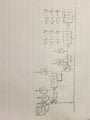
I'll add a basic schematic, but basically it's an astable 555, with a 1 minute cycle, with the 555 output providing the clock input for the first 4107. The first 9 outputs feed the first 9 LEDs. The 10th output feeds power to the next 4107 (and disabled the 4017), which uses the same clock output as the first. This lights up the last LED. The second output powers another astable 555 and 4107 (and disables further counting on the 4107).
(I know the datasheet recommends a different circuit to cascade 4107s, but since I don't ever need it to come back around to the first output, my implementation above seemed to be all I needed).
Now, I was worried about drawing too much current through the 4107s to power the later subcircuits, so I though, I'll run that output and use it to switch on a transistor, and that will be a better way of powering the further components. (Maybe this wasn't a problem, I'd be curious about this too. I could probably struggle through the calculations of what was necessary, but just figured this way, I'd just be safe.)
HERE IS THE PROBLEM and QUESTION.
I connect the 4017 to the base of the 3904 (though a base resistor), connect the collector to the power rail, and the emitter to power the subcircuit.
However, the voltage I get at the emitter is LOWER than the voltage from the 4107. This seems wrong to me.
For example, on the first transistor, the voltage out of the 4107 is 5.2v (this is the v on the power rail for the circuit). After the base resistor, I read 4.9v. At the emitter, I read 4.6v.
Shouldn't I be getting 5.2v, the rail voltage, at the emitter?
This problem gets worse at the next 4107 output/3904 transistor (i.e the voltages get even lower).
(For now, I've rebuilt this with a series of inverters built with these same 3904s -- inverting the 4107 output twice, giving me the rail voltage.)
The circuit works well (even with the basic transistors, it works, the LED is just dimmer than it could be), but I can't figure out why the transistors aren't acting as I'd expect. (For the record, I figured when the base gets powered, the transistor will "switch on" and give me the voltage of the rail at the emitter.) I also tried connecting the first transistor in a darlington pair (i.e. added a second transistor), but the voltage dropped even more (again, to my surprise).
Can anyone help me figure out what's going on here?
Thanks so much,
Luke
I'm prototyping a circuit and the 3904 transistors are not doing what I'd expect, and I'm not sure why. I was hoping maybe someone here could help me track down the problem, or just point out the problem with my thinking.
Here are the circuit basics. I'm basically building a countdown clock, which uses a 555 & 4107 to sequentially light up 10 LEDs, then flash the last LED a few times.
I'll add a basic schematic, but basically it's an astable 555, with a 1 minute cycle, with the 555 output providing the clock input for the first 4107. The first 9 outputs feed the first 9 LEDs. The 10th output feeds power to the next 4107 (and disabled the 4017), which uses the same clock output as the first. This lights up the last LED. The second output powers another astable 555 and 4107 (and disables further counting on the 4107).
(I know the datasheet recommends a different circuit to cascade 4107s, but since I don't ever need it to come back around to the first output, my implementation above seemed to be all I needed).
Now, I was worried about drawing too much current through the 4107s to power the later subcircuits, so I though, I'll run that output and use it to switch on a transistor, and that will be a better way of powering the further components. (Maybe this wasn't a problem, I'd be curious about this too. I could probably struggle through the calculations of what was necessary, but just figured this way, I'd just be safe.)
HERE IS THE PROBLEM and QUESTION.
I connect the 4017 to the base of the 3904 (though a base resistor), connect the collector to the power rail, and the emitter to power the subcircuit.
However, the voltage I get at the emitter is LOWER than the voltage from the 4107. This seems wrong to me.
For example, on the first transistor, the voltage out of the 4107 is 5.2v (this is the v on the power rail for the circuit). After the base resistor, I read 4.9v. At the emitter, I read 4.6v.
Shouldn't I be getting 5.2v, the rail voltage, at the emitter?
This problem gets worse at the next 4107 output/3904 transistor (i.e the voltages get even lower).
(For now, I've rebuilt this with a series of inverters built with these same 3904s -- inverting the 4107 output twice, giving me the rail voltage.)
The circuit works well (even with the basic transistors, it works, the LED is just dimmer than it could be), but I can't figure out why the transistors aren't acting as I'd expect. (For the record, I figured when the base gets powered, the transistor will "switch on" and give me the voltage of the rail at the emitter.) I also tried connecting the first transistor in a darlington pair (i.e. added a second transistor), but the voltage dropped even more (again, to my surprise).
Can anyone help me figure out what's going on here?
Thanks so much,
Luke
Attachments
-
 475.3 KB Views: 25
")


