Problem in circuit laplace and switch

Thread Starter

one(1)

Joined Oct 6, 2014
27
Hello again,

I see what happened here. The chicken scratch was too hard to read so i read the capacitor value as 1/0.8 Farads, not 1.25uf. The big "M" apparently was intended to show a multiplier by a factor of 1e6. This of course changes the solution. It's better to use notation like 1e6 or 1e-6 rather than "m" and "M". This happened with the current amplitude also, which i had mistaken for 15 amps not 15 ma in the beginning.

I'll repeat the values so we are all on the same page:
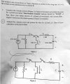
R=2000 ohms
L=0.8 Henries
C=1.25 microfarads
I=0.015 amps

The solutions then should matche the others:
Vc(s)=12000/((s+500)*(s+2000))
Vc(t)=8*(e^(-2000*t)-e^(-500*t))

So you can verify with this if you like.


The solution i was doing previously was for C=1.25 Farads, which comes out to:
Vc=4.8e-6*(e^(-0.0004*t)-e^(-2500*t))

which is actually a more interesting solution because the time constants are so far apart.
wow , very nice :)
 

MrAl

Joined Jun 17, 2014
13,702
Hi again,

Sorry i didnt catch that sooner, but that's what happens sometimes when the text isnt typed out neatly. Sometimes it is hard to tell the difference between characters like "S" and "5" for example.

Well now you have two examples to work with: the first with C=1.25uf and the second with C=1.25 Farads :)

Here's the worked out example using C=1.25 Farads:

Starting with the impedance for the R and C we have:
zRC=0.8/s+2000

That comes from summing the R and C impedances.

The impedance for L is:
zL=s*L=0.8*s

Next, put that in parallel with the impedance for R and C:
Z=zRC*zL/(zRC+zL)=(0.8*(0.8/s+2000)*s)/(0.8*s+0.8/s+2000)

which simplified a little is:
Z=(10000*s^2+4*s)/(5*s^2+12500*s+5)

Now to get the voltage at the top of the inductor, we multiply I
times this impedance:
vL=Z*I=(7500*s+3)/(250*s^2+625000*s+250)

Now that we know the voltage at the top of the inductor, we can get
the voltage across the cap by multiplying by zC and dividing by zRC:
vC=vL*zC/zRC=3/(250*s^2+625000*s+250)

and factoring out the 250 we get:
vC=3/(250*(s^2+2500*s+1))

The denominator is:
D=250*(s^2+2500*s+1)

so the roots are both real:
r1=-4.000000640000204*e-4
r2=-2499.99959999994

so the solution is in the form:
A*e^(r1*t)+B*e^(r2*t)

I rounded r1 and r2 to make a neater looking solution:
r1=-4e-4
r2=-2500

but you can keep the more accurate roots if you like.

Then A comes out close to -4.8e-6 and B comes out close to 4.8e-6
so we have:
Vc=4.8e-6*(e^(r2*t)-e^(r1*t))

or:
Vc=4.8e-6*(e^(-2500*t)-e^(-0.0004*t))
 
Last edited:

jarkky

Joined Jan 10, 2020
22
This looks slightly "crazy" task, because setting is as current source ramp up at t>0 (15/s mA) and switch moves at t=0 (switch moving before current source ramped up).
This could mean that Ix(t)=0 and v0(t)=0 for all t>=0sec.
 

jarkky

Joined Jan 10, 2020
22
This looks slightly "crazy" or impossible task, because setting is as current source ramp up at t>0 (15/s mA) and switch moves at t=0 (switch moving before current source ramped up and there is not good definition in laplace for switch moving at t=0). Laplace transform is not valid for t<0sec.
This could mean that Ix(t)=0A and v0(t)=0V for all t>=0sec.
Function 1/s used in switching moves 'switch' (or generates voltage ramp) after t>=0, but some references say after t>0.
I'm not sure if there is actual switching functions in laplace, but rather ramp voltage and ramp current sources.
The switching must be formulated by ramp sources.
If one combine impulse sources and ramp sources it could be best that the impulse sources (dirac delta) work exactly at t=t0 and switching would occur at t>t0 so that the impulse sources would not interfere with the switching.
 

jarkky

Joined Jan 10, 2020
22
But it could be just right to operate the switch at t=0 also, to get solution for I(t) at I(0) without step function.
I'm not sure if the step function and impulse function could interfere in bad manner if both operate exactly at t=0.
 

jarkky

Joined Jan 10, 2020
22
Screenshot from 2020-01-10 17-08-36.png
It could be very nice to know if the pulse source operates at t=0 to t=0+ so that at t=0 is connected to node A and t=0+ connected to node B (assuming switch could not connect two nodes at the same time).
 

MrAl

Joined Jun 17, 2014
13,702
Hello,

Usually in these scholastic problems it is acceptable to hold certain things like power sources in limbo where they are frozen in time even though something else is happening.
We see this all the time especially with current sources. We see them "open" before the switch is closed and that is acceptable even though the current source must have produced and held fast an infinite voltage until the switch was closed.

Consider the dual of the open current source: the shorted voltage source. It would be funny if we had to short every voltage source before t=0 and then open the short at t=0+.

The question comes up as to how to handle that situation and from what i see normally it is acceptable where we consider the current source to be "off" rather than open circuited.
Will all professors allow this? Only the individual can define what is acceptable, and we can only get that info from the OP. If they dont mention it, i assume the limbo source theory is in effect.
 

jarkky

Joined Jan 10, 2020
22
Screenshot from 2020-01-11 11-21-39.png
Current of capacitor disharging vs time... Sometimes the question and initial conditions is hard to be understood
and I don't know if question is correct, even that is best assumption. The calculation looks quite hard for this case.
 

jarkky

Joined Jan 10, 2020
22
How the switch operates could be various cases (even instantaneous).
For example position A at t=0-, no connection at t=0 and position B at t=0+.
But I guess position A at t=0 and position B at t=0+.
This could affect how the calculation is done, but couldn't affect the end results because dt is very small between t=0+ and t=0.
Basically I'm not sure about switching model in the Laplace.
 

MrAl

Joined Jun 17, 2014
13,702
Hello,

How are you getting a positive going initial response when the current is negative at t=0?

Here is the original problem statement and note the second switch.
The second image is my solution and graph.

Also, there is nothing wrong with stating the initial cap voltage as 0v and the unwritten rule is that if the initial current is not given then it either is zero (default) or has to be solved for. In this case we can say that the initial inductor voltage is not zero at t=0+ and fall back to the default cap voltage as zero volts.
 

Attachments

jarkky

Joined Jan 10, 2020
22
Hello,

How are you getting a positive going initial response when the current is negative at t=0?
Also, there is nothing wrong with stating the initial cap voltage as 0v
It depends on the 0.015/s timing what the initial current is.
If you draw the timing then it should be found in the timing.
I don't know the initial cap voltage. Most likely that would be 0v, because any
capacitor would leak into 0V during long waiting.
 

MrAl

Joined Jun 17, 2014
13,702
It depends on the 0.015/s timing what the initial current is.
If you draw the timing then it should be found in the timing.
I don't know the initial cap voltage. Most likely that would be 0v, because any
capacitor would leak into 0V during long waiting.
Hello, and i see you joined the forum just yesterday so WELCOME to the forum.

Can you show me how the initial current in the inductor can be anything other than 15ma?
(and of course that source points downward).

And for those interested, there is no Laplace for a switch. The switch has to be handled as different modes of the circuit which is sometimes called "realizing the switch" and this amounts to different topologies depending on the state of the switch and each topology is linear if the original circuit pieces minus the switch (and/or diode) were linear.
The different modes however can be found in different ways the most typical is by inspection but there are purely mathematical ways also.
 
Last edited:

jarkky

Joined Jan 10, 2020
22
Because some times the 1/s is 1 and sometimes its u(t) (depending on the table you use):
Screenshot from 2020-01-12 11-50-55.png
vs.
Screenshot from 2020-01-12 11-51-18.png
so if there is not drawn the timing one could guess case a.) or b.).
If you have the table a.) then make as that. And laplace would not be valid for t<0.
So I guess inverse laplace of the 15/s mA is 15mA*u(t), because '1' is valid for all t<0 and t>=0.
If laplace is not valid at t<0, inverse laplace should should give zero for that region.
If circuit is not given in the time domain one could not be sure what the 1/s means.
If it was given in time domain as 15mA that could mean 15mA for all t<0.
But if given in s-domain as 15/s mA that could mean 15mA*u(t) in time domain.
By using the s-domain definition only this is not certain what it means.
For any floating node initial value of 0V is possibly best assumption, but not 100% certain,
especially if node voltage is named as Vo(t) and Vo(0) numeric value is not given.
The s-domain has "information loss" in regards what happened before t<0. Therefore
one should know the t-domain behavior to be sure.
 
Last edited:

MrAl

Joined Jun 17, 2014
13,702
Hello,

Well there is the 2nd circuit in the original problem statement that shows that one switch opens and the other closes so it seems pretty straightfoward. Also, the cap is defined in what looks like the Laplace domain, and is the inductor, so it would make sense to call the 15ma source a step of 15ma unless the instructor wanted to get tricky.

If we allow any interpretation then what stops me from calling the 15/s ma source a well defined source as is and then going by the switches apply a step to that, so we end up with:
15/s^2
which of course is a ramp. If we allow random interpretations then we would have to allow that as a possibility too, but then we'd also have to take the cap and inductor "values' verbatim and apply that logic to them too, so the cap would become:
1/(C*s^2)
and the inductor:
L*s^2
which does not seem likely.

Note in the above when the cap value is "C" then the impedance is 1/(s*C) but if the cap value itself was somehow 1/(s*C) already then the impedance would have to be 1/(C*s^2).
So i believe they are stating impedances and the cap has value 1.25 microfarads so the impedance becomes 1/(1.25e-6*s).
 

jarkky

Joined Jan 10, 2020
22
Screenshot from 2020-01-12 18-05-56.png

I think it should just follow spice-simulation principles (where DC-analysis is performed before transient analysis).
 
Top