Printed Circuit Mount Low Power Transformer

du00000001

Joined Nov 10, 2020
191
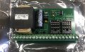
It popped? An aluminum cap?
My best guess: you put it in the wrong way - + and - interchanged.
Do you really know where the - pin should be placed and how to identify it on the cap?
 

Thread Starter

Recoil6

Joined May 23, 2021
33
Thank you for the replies gentleman :)
du00000001: Yes bud it did pop with an explosive poop of oil out of its tiny little bunghole! I was surprised since it didn't get that hot, I thought it worked since it didn't get as hot as the other caps but surprise, surprise! :(
The cap is clearly marked with arrows pointing +/- side, I even went as far as downloading pictures of the board to make sure I had it in the right direction.
MaxHeadRoom: I will give a go to those things when I get home.
Thank you gents!
 

du00000001

Joined Nov 10, 2020
191
Thank you for the replies gentleman :)
du00000001: Yes bud it did pop with an explosive poop of oil out of its tiny little bunghole! I was surprised since it didn't get that hot, I thought it worked since it didn't get as hot as the other caps but surprise, surprise! :(
The cap is clearly marked with arrows pointing +/- side, I even went as far as downloading pictures of the board to make sure I had it in the right direction.
MaxHeadRoom: I will give a go to those things when I get home.
Thank you gents!
Al caps do not get that hot (other than TA caps they do not start burning), but they build up pressure. Usually relieved via the pressure relief valve, but I've once had the whole aluminum can flying...
Better check the voltage without the cap - there's something weird: either the voltage is way too high, or your rectifier diodes do not do what they are expected to do.
This is the point where a scope is required - to check for AC vs. DC and amplitude.
 

Thread Starter

Recoil6

Joined May 23, 2021
33
Al caps do not get that hot (other than TA caps they do not start burning), but they build up pressure. Usually relieved via the pressure relief valve, but I've once had the whole aluminum can flying...
Better check the voltage without the cap - there's something weird: either the voltage is way too high, or your rectifier diodes do not do what they are expected to do.
This is the point where a scope is required - to check for AC vs. DC and amplitude.
Ya that is what happen bud. The voltage without the cap is 38.6v in AC, if I try to measure in DC I do not get any voltage, weird to me since I thought it would be DC.
If I am understanding you correctly now is time to check the diodes, I will do this along with MaxHeadRoom last suggestion. Thank you!
 

MaxHeadRoom

Joined Jul 18, 2013
30,688
I would disconnect the rectifier(s)/bridge etc and just measure the AC conductors on the TFMR secondary.
is shows as a 8v - 16v dual CT output secondary.
 
Last edited:

Thread Starter

Recoil6

Joined May 23, 2021
33
I did remove the diodes from the bridge and measured how much voltage there is across the diodes it fluctuated up and down but it was around 6.6v, 4.9v, 5.5v and 4.4v for each diode bridge. I did solder new diodes in the bridge and measured across the cap it dropped from 38.6v to 17.77v! I measured the coils in the transformer both coils were 10v before they went up by a little bit to 10.33 in both of them. Anyhow, I felt pretty confident that the diodes were bad since it dropped to 17.77v. I put a good cap back on the board and power it up to my surprise one of the diodes went up in smoke and the cap started to heat up and that is where I unplugged it.
Before you guys ask yes I did observe the polarity of the diodes I took a picture before I took them off the board. And yes I put the cap in the right direction too.
Well I hope you guys can give me more ideas to try. Thank you!
 

du00000001

Joined Nov 10, 2020
191
"good cap" = Ta cap rated 35 V ?

Where did you get this cap from? Any chance it might be a mis-labeled one?
From your description, a short (or overloaded) cap might have ruined one or kore diodes.

What about attaching the next cap to some lab power supply (@ e.g. 30 V) to make sure it can withstand the voltage? Prior soldering it to the PCB.
 

Thread Starter

Recoil6

Joined May 23, 2021
33
"good cap" = Ta cap rated 35 V ?

Where did you get this cap from? Any chance it might be a mis-labeled one?
From your description, a short (or overloaded) cap might have ruined one or kore diodes.

What about attaching the next cap to some lab power supply (@ e.g. 30 V) to make sure it can withstand the voltage? Prior soldering it to the PCB.
This is one of the new caps that I bought originally (35v) clearly labeled same as the cap that was on the board before. I do not have a lab power supply unfortunately, I did test it with my voltmeter and it did charge.
 

Thread Starter

Recoil6

Joined May 23, 2021
33
Well guys it failed again :( I changed the voltage regulator (MC78M12CT), diodes and cap. Now that I know how components fail under power I put power to the board feeling the temperature of the diodes and I can feel them getting really hot and cut the power before anything pops.
All those parts are new and I am going to assume working, the transformer still putting out 10v in every coil, I am measuring 37.5v at the capacitor.
needless to say I am lost and have no clue what to try next. Thank you all for any suggestions you might have.
 

SamR

Joined Mar 19, 2019
5,494
Do you have the schematic diagram? I'd start at the XFMR and measure the input and output with the output disconnected. Then reconnect and go the the next stage, the rectifier, same thing, disconnect it from its output and measure its input and output. Be careful to check each polarized component for proper installation. Keep going to the next block and repeat. Explosive popping of caps is indicative of reversed polarity. Undervoltage caps usually get hot and spew, not pop explosively unless seriously mismatched. Smoothing caps will hold/pull the voltage higher as it smoothes the rectified AC. There are not that many stages to a power supply... Is the board damaged? Signs of liquid stains or burnt component carbon tracking? Traces intact?
 

Thread Starter

Recoil6

Joined May 23, 2021
33
Do you have the schematic diagram? I'd start at the XFMR and measure the input and output with the output disconnected. Then reconnect and go the the next stage, the rectifier, same thing, disconnect it from its output and measure its input and output. Be careful to check each polarized component for proper installation. Keep going to the next block and repeat. Explosive popping of caps is indicative of reversed polarity. Undervoltage caps usually get hot and spew, not pop explosively unless seriously mismatched. Smoothing caps will hold/pull the voltage higher as it smoothes the rectified AC. There are not that many stages to a power supply... Is the board damaged? Signs of liquid stains or burnt component carbon tracking? Traces intact?
Unfortunately, I do not have the schematics for the board. The transformer is soldered into the board and is going to be a pain to remove for testing but I will if need it.
Before the cap pops there is one diode that pops first, after that diode pops then the cap goes.
The board looks like new, with no signs of liquid damage, stains, carbon or any other signs of damage.
 

Thread Starter

Recoil6

Joined May 23, 2021
33
Test first then replace. How much of those tantalum caps is there on the PCB? Any chips? Can you post a picture of both sides of the whole PCB?
There is only one of those capacitors, there is one chip "DN811L LM393". I have this one picture of the front, I will post the back when I get home later this evening. Thanks!
 

Attachments

Thread Starter

Recoil6

Joined May 23, 2021
33
Diode shorts because too much current goes thru. Dit you mesure any semiconductors after the cap?
Before I put the cap on the board I did measure the diodes and I was seeing 17v across each diode if memory serves me well.. I did not measure anything else tho.
 

Thread Starter

Recoil6

Joined May 23, 2021
33
Your picture shows 2 such caps? The LM393 is probably also damaged from all those over voltages.
I apologize Anniel, yes there are the smaller caps what I meant is the big cap there is only one. I am attaching an image that shows the cap. The other one has the cap removed.
 

Attachments

Top