 Facebook
 Google
 GitHub
 Linkedin
I am attempting to design a DC-AC inverter for my third year project. I have successfully simulated the inverter on PSIM with an inner loop current controller and an outer voltage control loop (see attached images). However, when I attempt to use op amps for the PID circuit, the simulation just doesn't run as desired. I get a constant dc 5V output. Kindly help in this regard.
Parameters:
Input voltage = 400V output = 230 rms, 50Hz. Switching freq = 50khz.
1st image: conceptual design
2nd image output of conceptual design
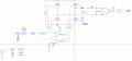
3rd image pid using op amps (does not run as desired).
Integral time constant = R9C3
Proportional gain = R9.R10/(R8.R11)
All unspecified resistances are 10k.
Parameters:
Input voltage = 400V output = 230 rms, 50Hz. Switching freq = 50khz.
1st image: conceptual design
2nd image output of conceptual design
3rd image pid using op amps (does not run as desired).
Integral time constant = R9C3
Proportional gain = R9.R10/(R8.R11)
All unspecified resistances are 10k.
Attachments
-
 35.5 KB Views: 15
 -
 39.3 KB Views: 15
 -
 212.6 KB Views: 16


