Powering servo's and a solenoid in a jumping Robot

Thread Starter

bartfriederich

Joined Mar 31, 2017
10
Hello,

For a course in mechanical engineering, we are building a jumping robot. The actual jumping movement will be powered by pneumatics, however we are using a 24V solenoid-valve to power the actuator, and some servo's to get the robot upright again.
Note: The robot will only need to jump twice (though more jumps would be nice)

Servo's
Weight is quite an issue, so right now we are having some struggles trying to find a good power source for the electronics.
We will use two small servo's (they use 300mA each) and one big servo (0.25A running and 2.5A stall current!!!), though none of them will be used at the same time. The servo's run at 5V.

Solenoid
The solenoid will be a 0.9Watt 24V solenoid (~40mA) and it will only be switched on for about 0.5s for each jump (~0.5 Joule per jump)

Our Plan
The whole system will be controlled by an arduino nano.We were thinking about using 3x 9V batteries in series to power the solenoid, and using a voltage regulator to bring that down to 5V for the arduino and the servo's.

Problems
The first big unknown is how much current the big servo would actually take. We calculated that the torque we need will be about 70% of the stall torque at its peak.
When our voltage regulator is about 90% efficient, that would mean the batteries would have to deliver about 600 mA when the servo does the hardest work. Is this something that could be achieved? For the batteries, we were looking at the "Industrial by Duracell 9V". We are hoping it will at least work once or twice until the batteries are dead.
Another option would be to use lower voltage batteries (maybe LiPo's?) and somehow convert that to 24V for the solenoid.

Note that we are also open for some other suggestions, however weight is an important issue, as well as costs.
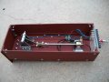
totaal_zonder_case.JPG
 

Thread Starter

bartfriederich

Joined Mar 31, 2017
10
I can't edit the above, but just after posting this thread I tried to find some more info on LiPo's and it really seems the way to go.
I'm thinking maybe a 7.4V 1000mAh 2S LiPo which will have to be converted to 5V ofcourse, I think the LM1085 would be fine for that purpose.

Do you guys think it is a reasonable plan to use a step-up regulator to get the to 24V for the solenoid valve? If so, do you have any recommendations?
Another option might be using some sort of capacitor pump, which might be more elegant but if a simple step-up regulator will do, I'd much prefer that.

I'll of course have to integrate some sort of battery voltage indication (to prevent over-discharging) into the arduino but that really should be a piece of cake using two resistors as a voltage divider and one of the Analog Inputs.

Greetings,
Bart
 

djsfantasi

Joined Apr 11, 2010
9,237
Using step-up regulator will require more current from the battery. To get 40mA out requires 130mA in. The rules of Ohms law and conservation of Power cannot be be broken. Sorry.
 

Thread Starter

bartfriederich

Joined Mar 31, 2017
10
Using step-up regulator will require more current from the battery. To get 40mA out requires 130mA in. The rules of Ohms law and conservation of Power cannot be be broken. Sorry.
I suppose I wasn't clear enough; right now the plan was using a step-up regulator in combination with a 7.4v lipo. (In that case current wouldn't be a concern considering the high discharge capabilites of a lipo cell)
 

Bernard

Joined Aug 7, 2008
5,784
Sounds familiar, both methods were used to lift targets. Pneumatic required 24 V for valve & was provided
by a boost circuit driven be 4 AA NiMH batteries rated @ 2600 mAh. giving a stable 5 V. The servos also driven from 5 V.Air Lift  Bottom 2 00000.JPG
 

crutschow

Joined Mar 14, 2008
38,593
You might try charging up a large capacitor with a small 24V boost regulator to operate the solenoid.
The means the regulator wouldn't have to supply the total solenoid current, just the small charging current between jumps.
Start with about 1,000-2,000μF or so charged to 24V, to see if that will operate the solenoid for a sufficient length of time.
 

Thread Starter

bartfriederich

Joined Mar 31, 2017
10
That would indeed be a good idea, using a cap with a voltage regulator. Maybe I could also use 5-24V DC-DC converter (Datasheet: https://www.digchip.com/datasheets/download_datasheet.php?id=263335&part-number=DC/DCSIM1-0524-SIL4) with a cap; to keep my circuitry simple. It's been a while since i've done a somewhat more complicated project like this (there are also some buttons and signal led's involved) and I'm afraid it might get a bit too challenging.

Another way to solve this might be using an MT3608 module (Datasheet: https://www.olimex.com/Products/Breadboarding/BB-PWR-3608/resources/MT3608.pdf). It would keep my circutiry a bit less complicated; do you guys think it would work for the solenoid valve?
 

crutschow

Joined Mar 14, 2008
38,593
That would indeed be a good idea, using a cap with a voltage regulator. Maybe I could also use 5-24V DC-DC converter (Datasheet: https://www.digchip.com/datasheets/download_datasheet.php?id=263335&part-number=DC/DCSIM1-0524-SIL4) with a cap; to keep my circuitry simple................

Another way to solve this might be using an MT3608 module (Datasheet: https://www.olimex.com/Products/Breadboarding/BB-PWR-3608/resources/MT3608.pdf). .............
The first is a self-contained module which looks like it should work for your requirements.

The second will require some design work and careful circuit layout so wouldn't be as easy to use.
 

Thread Starter

bartfriederich

Joined Mar 31, 2017
10
The first is a self-contained module which looks like it should work for your requirements.

The second will require some design work and careful circuit layout so wouldn't be as easy to use.
Actually I found a ready-to-use module, much alike this one:

I think this would be a good idea to use, a bit more reliable than the last few options as well. I might use a buck converter instead of the LM7805 aswell, since it is rated much better for high loads.

What do you guys think?
 

crutschow

Joined Mar 14, 2008
38,593
Those should work for you.

You don't really need a buck converter for the +5V unless you are concerned about battery life, since a linear converter has an efficiency of 5/7.4 = 67.6% for those voltages.
A buck converter would likely have an efficiency of about 85-90%.

Note that the above converter is apparently a boost converter, not a buck converter, so it won't generate a voltage below the battery voltage.
 

Thread Starter

bartfriederich

Joined Mar 31, 2017
10
I'm going with both a buck converter and a boost converter, I found some very cheap ones with all the capacitors and things already in. By replacing the 5V linear converter for this one, I can also set my servo's at 6V instead of 4.8, which gives me an additional 20% torque. An adjustable linear converter would have been quite a hassle with all the resistors and capacitors and what not.

I'm using 5V relay with a 120ohm coil to switch the solenoid valve. I'll feed it from the 6V rail and put a 1W resistor in series to get to the 5V. The value of the resistor will be determined by trial and error so I can also compensate for the voltage drop in the BC337 that I'll use to switch. Does anyone know what base resistor I'll need for it?

I'll give you guys an update when everything's in and I get it working, thanks so far!
 

Bernard

Joined Aug 7, 2008
5,784
I = 5V/ 120 ohms = 41.67 mA. I base = 1/10 coil current or 4.2 mA. R = 6V - .6 V = 5.4 V / .oo42 = 1285 or closest = 1.2k. W = I x A = .042 x 1 = 42 mW= 1/8 or 1/4 W.
 

Thread Starter

bartfriederich

Joined Mar 31, 2017
10
Hello guys! So, I got it all rigged up today, and it functioned just fine. The setup is shown on in the picture below:

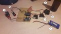
(Almost) Complete Test Setup: 1) 7.4V LiPo Battery 2) 20kg*cm 6V Servo 3) 2x Slimwing Servo 4) Solenoid for operating valve 5) NC Startbutton 6) Delicious Brand Beer
20170414_002939.jpg

So, you might have noticed the past tense when I say every thing "worked" fine... Well, it did... untill Murphy's law kicked in. The great Murphy said: "When there is two ways to plug in your battery, sooner or later you'll goof up and plug it in the wrong way." Sadly the column of smoke rising from my Buck- & Boost converters was not caught on camera. It looked somewhat like the monster from Lost. My piezo buzzer was making a fitting sound as well.

Lesson: Don't use a simple header to connect your LiPo. Aftermath: New Buck- and boost converters, new arduino nano AND last but not least: A female JST header to connect the LiPo with. Score: -€12.50. Can't put a price on a good lesson though.

For those interested, I'll explain the circuitry

print.jpg

Workings:
1) Power inlet via 2 simple headers, to be replaced by a female JST plug
2) Boost Converter, converts the inlet to 12V for the solenoid
3) Header for the solenoid (polarity is not important for this one)
4) Flyback diode hidden underneath the boost converter
5) 5V Relay
6) Relay driving circuit, consisting of a flyback diode for relay coil, a BC337 and a resistor
7) Resistor which brings the 6V supply voltage down to 5V for the relay-coil
8) Arduino Nano
9) Launch button connector
10) Connections for signal-lights
11) Piezo buzzer which will sound before the robot launches
12) Adjustable Buck-converter which brings the LiPo battery voltage down to 6V for the servo's (can deliver 3A peak, big servo uses 1.5A peak)
13) Connection headers for servo's (maybe find a way to prevent plugging them in the wrong way as well)
14) Place where an MPX5700 pressure module can be placed

So what I think needs to be replaced is only the arduino and the converters. The arduino seems to be working ok, except for the power regulator (which now delivers 3.7V vs 5V?) but I don't want to take any chances.

Improvements to be made:
*Make sure there's only ONE way to insert essential plugs
*Add a fuse (I don't want my LiPo blowing up on me when something shorts)
*Add a capacitor before the solenoid to avoid voltage drops when solenoid activates

Any more I can add??

Thanks so far for your help, the circuit seems to be functioning great (if everything's plugged in the right way ;)).

Greetings,
Bart
 

crutschow

Joined Mar 14, 2008
38,593
Murphy is an unpaid engineer on every job. :rolleyes:

If you had said there was a non-polarized plug for the battery, we would all have collectively said, "Noooooooooo....". :eek:

An alternate to a polarized plug is a series diode to block any reverse polarity (or if you don't want the diode voltge drop, a MOSFET connected as an ideal diode).
 
Last edited:

Thread Starter

bartfriederich

Joined Mar 31, 2017
10
So far most things are going well, except for powering the big servo. As it turns out, te current needed for the big servo is too high (or at least that's what I'm assuming), causing the buck converter to quit while the robot tries to stand up.
After reading back, I now realize the buck converter probably delivers a lot less than the 3A peak current, and raising the robot probably takes more time than what they call "peak".

Alternatives are endless ofcourse, but I need something quick and easy. The servo I'm using is rated for 4.8-6.6 volts, and my battery runs at 8.4 to 7.0V (that's when my arduino gives a low-battery alert). My idea is to feed the servo from the LiPo directly, while using a big ass diode to bring down the voltage.

I have a bunch of diodes, but the big ones are the 1N5408 and the 1N5822 . The 1N5408 is rated at 3A forward current, and gives between 0.7 and 0.8V voltage drop in the current range I'll be using it in. What do you guys think, would using 3 of these in series work for me?

Greetings,
Bart
 
Top