 Facebook
 Google
 GitHub
 Linkedin
Hello ")
So first let me explain what i am doing:
I'm triyng to build an exponential VCO with this project: https://www.allaboutcircuits.com/projects/diy-synth-series-vco/
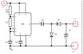
I need a dual power supply so i have built this circuit (NE555 version) https://www.allaboutcircuits.com/uploads/articles/NVG555.jpg from this tutorial: https://www.allaboutcircuits.com/projects/build-your-own-negative-voltage-generator/
But now i have a few questions because i prefere to be sure of what i'm doing.
In the negative generator circuit i have three outputs: V+, V- and the ground (GND). Now my problem is how to link this to my VCO ?
I don't understand how to link the negative generator to OP-AMP of the VCO.
First i'm not sure to understand the schematics:
Then:
You can find the schematic of the exponential VCO and the negative voltage generator in attachment.
Thank you in advance for your kind consideration of this request. English is not my native language so it's quite hard to speak with all the complicated vocabulary of electronics. So If something is unclear or further information is required to respond to a specific item, seek clarification and ask questions.
So first let me explain what i am doing:
I'm triyng to build an exponential VCO with this project: https://www.allaboutcircuits.com/projects/diy-synth-series-vco/
I need a dual power supply so i have built this circuit (NE555 version) https://www.allaboutcircuits.com/uploads/articles/NVG555.jpg from this tutorial: https://www.allaboutcircuits.com/projects/build-your-own-negative-voltage-generator/
But now i have a few questions because i prefere to be sure of what i'm doing.
In the negative generator circuit i have three outputs: V+, V- and the ground (GND). Now my problem is how to link this to my VCO ?
I don't understand how to link the negative generator to OP-AMP of the VCO.
First i'm not sure to understand the schematics:
- Is all the op-amp of the "linear to exponential" circuit connected like this: VCC in the pin Vs+ / VEE in the pin Vs- ?
- Is all the op-amp of the "VCO" circuit connected like this: VCC in the pin Vs+ / GND in the pin Vs- ?
Then:
- Is the V+ output of the negative generator the VCC of the VCO ? (If it's true i need to do something because it's not 5V ?)
- Is the V- output from the negative generator the VEE of the VCO ?
You can find the schematic of the exponential VCO and the negative voltage generator in attachment.
Thank you in advance for your kind consideration of this request. English is not my native language so it's quite hard to speak with all the complicated vocabulary of electronics. So If something is unclear or further information is required to respond to a specific item, seek clarification and ask questions.
Attachments
-
36.4 KB Views: 12
-
36.4 KB Views: 7
-
 104.5 KB Views: 11
Last edited:


