Powering leds from a power bank- they go dim

Thread Starter

MissOrange

Joined Nov 7, 2014
18
So it’s lockdown here and I’m making do with what I have in trying to experiment.
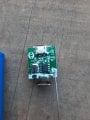
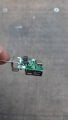
My goal is to understand how long a 5.3v 1000mah power bank would light up two leds. Leds have a forward voltage of 2.7v. I only have 100 ohm resistors.The circuit is parallel. Two leds each with a 100ohm resistor attached to positive and negative on the power bank. When I first plug them in the brightness is good and the light on the powerbank lights up. After a few seconds the light in the powerbank turns off and the leds go dim. Happens same each time I replug in. I’m wondering if I need to consider the other cables inside the USB cord - there are 5 in total, and I’m only using two, wondering if it’s a data connection that needs to be made for it to stay fully on? Or is it a current or ohms issue?
 

scorbin1

Joined Dec 24, 2019
103
Some power banks expect to be used for one purpose and one purpose only, and that's charging a phone. If it doesn't see the right amount of current draw, it assumes the phone is done charging and cuts off the voltage. This is likely what your seeing. It's kind of hard to say what that current limit is, but you could start adding 100Ohm resistors accross the powerbank's output to give it more of a load. However that kind of muddies the results of the experiment as it will obviously have a direct effect on the amount of supply as any power through the new resistors is 100% wasted.

100 ohm resistors on the LEDs will give you about 26mA through each LED for a total load of about 50mA. Depending on the LED, many these days can handle more current. If the LEDs are capable you could add a 100 Ohm resistor in parallell with each of the existing 100Ohm resistors and double the current to each LED for a total pull of 100mA. That might be enough of a load for the power bank to stay on, and the power through the new resistors wouldn't be entirely wasted as in the case of adding resistors accross the battery bank as suggested in my 1st paragraph.
 

dl324

Joined Mar 30, 2015
16,909
When I first plug them in the brightness is good and the light on the powerbank lights up. After a few seconds the light in the powerbank turns off and the leds go dim. Happens same each time I replug in.
The powerbank might not support having non-compliant devices attached. Measure the voltage across the LED+resistor before and after the LED dims.
 

Thread Starter

MissOrange

Joined Nov 7, 2014
18
Some power banks expect to be used for one purpose and one purpose only, and that's charging a phone. If it doesn't see the right amount of current draw, it assumes the phone is done charging and cuts off the voltage. This is likely what your seeing. It's kind of hard to say what that current limit is, but you could start adding 100Ohm resistors accross the powerbank's output to give it more of a load. However that kind of muddies the results of the experiment as it will obviously have a direct effect on the amount of supply as any power through the new resistors is 100% wasted.

100 ohm resistors on the LEDs will give you about 26mA through each LED for a total load of about 50mA. Depending on the LED, many these days can handle more current. If the LEDs are capable you could add a 100 Ohm resistor in parallell with each of the existing 100Ohm resistors and double the current to each LED for a total pull of 100mA. That might be enough of a load for the power bank to stay on, and the power through the new resistors wouldn't be entirely wasted as in the case of adding resistors accross the battery bank as suggested in my 1st paragraph.
Thankyou so much for your answer
 

Thread Starter

MissOrange

Joined Nov 7, 2014
18
Doesn't sound like a current issue, so I guess it could be a USB power negotiation issue or such.

Do you have a data sheet you could post?
Thankyou for your answer,
Doesn't sound like a current issue, so I guess it could be a USB power negotiation issue or such.

Do you have a data sheet you could post?
I took it apart in lieu of a data sheet as it is cheap and unbranded
 

Attachments

MisterBill2

Joined Jan 23, 2018
18,461
My reading of yhe setup in post #1is that the resistors are across the power bank, not in series with the LEDs. And that makes no sense at all. Put the two LRDs in series across the power bank and see what happens..Probably more light for a longer time. AND, use an accurate volt meter to monitor the voltage..
 

Thread Starter

MissOrange

Joined Nov 7, 2014
18
My reading of yhe setup in post #1is that the resistors are across the power bank, not in series with the LEDs. And that makes no sense at all. Put the two LRDs in series across the power bank and see what happens..Probably more light for a longer time. AND, use an accurate volt meter to monitor the voltage..
Would you mind explaining what a resistor across the power bank would look like?

If each led is 2.6v and supply power is 5.3v, then is it correct that it’s not possible to do series and have to do parallel?

The measurement (at the moment now I’ve taken the battery out of the USB interface and connected it to the leds with resistors) which I believe is in parallel but I’m very much learning)is 1.3v across each resistor and 2.6v across each led.
 
Last edited:

Sensacell

Joined Jun 19, 2012
3,442
The power bank is going to sleep- the voltage regulator inside burns power, they make them shut down to prevent self draining the battery.

Your light circuit draws less than the expected normal load.

You could increase the power drain which would be wasteful of power.

You might create a circuit that "wakes up" the regulator with intermittent bursts of power demand.

No easy fix.
 

MisterBill2

Joined Jan 23, 2018
18,461
The 2.6 volts on each LED is a nominal value at the design current. Two LEDs in series will certainly illuminate with a bit less voltage. And the internal resistance of the supply will limit the current a bit.
So try it with the two LEDs in series across the supply and no resistors in the circuit.
 

Thread Starter

MissOrange

Joined Nov 7, 2014
18
The power bank is going to sleep- the voltage regulator inside burns power, they make them shut down to prevent self draining the battery.

Your light circuit draws less than the expected normal load.

You could increase the power drain which would be wasteful of power.

You might create a circuit that "wakes up" the regulator with intermittent bursts of power demand.

No easy fix.
Thanks for your reply. If the rated output of the powerbank is 1000ma should I put enough leds on that draw 1000?
 

Tonyr1084

Joined Sep 24, 2015
7,894
My reading of the setup in post #1 is that the resistors are across the power bank, not in series with the LEDs.
My take on this statement is that there is one LED and one resistor paralleled with yet another LED and one resistor.
So try it with the two LEDs in series across the supply and no resistors in the circuit.
Forgive my ignorance, but isn't that a dangerous proposition? You need to limit the current otherwise you can burn up the LED's.

MissOrange If you have the materials to create yet more LED/Resistor circuits you can parallel them into your circuit as well. More light and you will draw a little more current. That might be enough current to make the power bank think it's doing a job.

Give me a few minutes and I'll post a schematic of what I believe you have going on; and what my recommendation(s) is(are).
 
Last edited:

Tonyr1084

Joined Sep 24, 2015
7,894
OK, I got the impression you have two LED's in parallel, each with its own resistor. That's the right way to do it. You can add more parallel circuits to your design, provided you have the materials. In your set-up you are drawing only 46mA from the power block. It's not seeing a need for charging so it's going back to sleep, as others have already said. I don't know what the minimum draw will be to keep the power block active. You might try adding more parallel LED circuits such as in the drawing below. This is significantly more current being drawn (138mA) as opposed to what yours is currently drawing (46mA). The reason why others have suggested adding another load resistor across the power block is to draw more current - possibly enough to keep it turned on. But also, as they've said, you're wasting that much energy as heat. Rather than adding a wasteful resistor, add more LED's to your power block and see if that keeps it turned on. As for adding a single resistor across the power block, you might consider that for experimentation purposes only. Once you know how much current is required to keep the block awake then you'll know how many LED's you'll need to turn it on and have it stay on. And it might not take as many as six LED's. It might take fewer. It Might take more. Experiment and see what happens. Only don't put two LED's in series without a resistor and expect anything good to happen.
1630161446826.png
 

Audioguru again

Joined Oct 21, 2019
6,688
The power bank is not rated at 1000mA. That is its absolute maximum do-not-exceed allowed current. Its rated current is the typical current it produces which might be 200mA or less.
 

MisterBill2

Joined Jan 23, 2018
18,461
For starters, two of these LEDs in series adds up to 5.6 volts. So if the source is 5.0 volts the LEDs will draw quite a bit less than the rated current.So no current limiting resistor is needed. And if you are able to supply just exactly the rated voltage, the current will be very close to the claimed forward current.
 

Tonyr1084

Joined Sep 24, 2015
7,894
The power bank is not rated at 1000mA. That is its absolute maximum do-not-exceed allowed current. Its rated current is the typical current it produces which might be 200mA or less.
AG: I was trying to make a point that the LED's and resistors will draw only as much current as they will. Even if the power source is 1,000 amps. A thousand amps is absurd, but it's intent is to make the point that the circuit will only draw as much current as ohms law predicts.
For starters, two of these LEDs in series adds up to 5.6 volts. So if the source is 5.0 volts the LEDs will draw quite a bit less than the rated current.So no current limiting resistor is needed. And if you are able to supply just exactly the rated voltage, the current will be very close to the claimed forward current.
Why do you keep going back to series LED's?
The circuit is parallel.
Now; to reiterate - if the power bank is not seeing sufficient current draw then - as others have said - it will shut down to preserve its charge. Two parallel LED's and associated resistors (see post #16) are drawing only 46mA. That may not be enough to keep the power bank active.

I have successfully run seven LED's in parallel ALL THROUGH A SINGLE RESISTOR. I don't get thermal runaway. The key was the LED's must be extremely closely matched. A secondary key is that if only one LED is operating it's operating at the proper current - as explained in the video I made some years ago. IF the resistor in my video would allow more current than one LED can handle then yes there would be thermal runaway and failure. With multiple LED's on a single resistor, the thermal runaway would be followed by cascading failure. A failed LED would be the same as an open LED (or removing it from circuit). Since a single LED and resistor does not fail there can be no cascading failure of the rest of the LED's. Please watch the 4 1/2 minute video.
 
Last edited:
Top