Powering ESP32 with 7.4V battery. PCB Design review

Ya’akov

Joined Jan 27, 2019
10,274
Thanks for the reply.
1. A buck converter is definitely a better solution, and I plan to switch to it. However, I’d like to first understand the root cause of the problem. I used standard capacitor values, which are commonly found on modules using these regulators.
2. I’m not familiar with the watchdog. If it needs to be enabled manually, it’s likely not running. Could you please tell me more about it?
A watchdog is a piece of hardware that periodically checks to see if the processor has locked up, in which case it drives the reset pin and reboots it. There are watchdog timers built in to the ESP32, but the one that would work for this—RTC_WDT (Real Time Clock Watchdog Timer)—is used for watching the boot process and resetting if it seems to hang.

A simple way to make one for your application is using a little 8-pin MCU (PIC, ATTiny, &c). You have an interrupt-based routine in your program pulse a GPIO pin that is connected to the outboard MCU—this is a heartbeat. The program on the external part has a countdown timer that is reset by the pulse, if it doesn’t happen in time, the program uses the ESP32 reset to reboot the chip.
 

Thread Starter

statieva

Joined Nov 27, 2024
40
Are you still having the issue with the relay "ticking"?
Yes, it persists. And it's indeed caused by ESP32 sending data because when I turn off this function in code - ticking disappears. I am thinking about adding a bulk decoupling capacitor. Any other ideas on how to resolve this ticking issue?
 

Thread Starter

statieva

Joined Nov 27, 2024
40
May need to experiment with the value of C30.
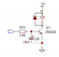
I changed R15 to 3.3k and tested different values for C30. With 10 µF, 4.7 µF, and 1 µF, the relay activates for no obvious reason, even though the transistor's base is set to LOW. Adding a 0.1 µF capacitor has no noticeable effect—the relay doesn’t activate, but the ticking persists. Would it make sense to try capacitor values between 0.1 µF and 1 µF? I also tried to pulldown the transistor base with a 10k resistor, but nothing has changed.

Now, I’m facing another issue. When I add a flyback diode, the relay activates as well. I’ve tested 1N4007, 1N4148, and 1N5819, all with the same result. I connected the cathode to the positive terminal of the coil and the anode to the negative terminal. To rule out any MCU damage from my previous attempts (where the relay operated without a flyback diode), I assembled a new PCB with fresh components, but the issue persists.

Any idea what could be causing this relay behavior?
 

sghioto

Joined Dec 31, 2017
8,729
Correct. What baffles me is how connecting a diode to the coil activates the relay without a GND connection. Yet, the relay and transistor work perfectly without the diode.
Is the circuit with the capacitor on the base and a diode across the relay working or not?
 

sghioto

Joined Dec 31, 2017
8,729
Do you have a meter do get some test readings?
Something is definitely defective or wired incorrectly.
 
Last edited:
Top