Powering a 4pin 12v fan with NE555 timer based PWM

Thread Starter

happirt

Joined Aug 12, 2017
18
I am trying to power a 4pin 12v fan using an external PWM controller (NE555 timer based). I have the fan connected directly to a 12v power source and the pwm pin connected to a PWM controller to control the fan speed, but it is not working.
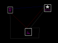
fan pwm.png

Apologies for the amateur diagram. The blue line represents pwm power going to fans 4th pin, but the 555 timer is at a constant 12v instead of pulsing. I think the problem is the ground from 555 timer but I dont know where to connect it. Please advise.

This is the pwm controller I am using
https://www.ebay.com.au/itm/12V-DC-...e=STRK:MEBIDX:IT&_trksid=p2060353.m2749.l2649
 

Reloadron

Joined Jan 15, 2015
7,882
On the most common 4 wire fans as seen in home computers and such the fan will have a +12 Volt wire, a negative common wire, a Tachometer Out wire which is normally 2 pulses per revolution of the fan and a PWM input wire to the fan. Connect the +12 Volts and Ground wires. Now touch the PWM input wire to +12 Volts does the fan run full speed, now touch the PWM wire to Common does the fan run? Most fans like this have an internal FET and you want to know if speed control is N channel or P channel. Your 555 PWM signal should share the same common (negative) as the fan. So what happens when you place the PWM into the fan on +12 V and when you try common?

Ron
 

Thread Starter

happirt

Joined Aug 12, 2017
18
When I connect PWM into fan on +12v I can control speed.
when connected to ground it will run at lowest speed (working as expected)
when connected to 4th pin (PWM) it is full speed.

The PWM controller has +12v and -12v IN and +12v and -12v OUT (I accidently left the -12v OUT in the diagram)
The -12v IN is connected to common ground.
I don't know where to connect the -12v OUT from the PWM. If I connect to common ground it will not pulse.
 

Thread Starter

happirt

Joined Aug 12, 2017
18
I have updated the diagram, hoping someone can help.

fan pwm2.png
I think the problem is the green ground connection but I don't know where else it belongs...Hoping someone can help...
 

ericgibbs

Joined Jan 29, 2010
21,437
hi,
The 0v look OK, but what about the fan pin #3.
Clip:
A PWM-capable fan is usually connected to a 4-pin connector (pinout: Ground, +12 V, sense, control). The sense pin is used to relay the rotation speed of the fan and the control pin is an open-drain or open-collector output, which requires a pull-up to 5 V or 3.3 V in the fan.
 

Thread Starter

happirt

Joined Aug 12, 2017
18
I dont think i need pin3,

I think it is the ground because

With my diagram the controller sends a constant 12v (not pulsing) to pin4. if i remove ground connection from battery to fan and rather connect the ground from fan to controller instead, then controller sends pulse to both pin1 and p4 ...?

Is the PWM controller switching ground instead???
 

Thread Starter

happirt

Joined Aug 12, 2017
18
Is there a way for me to use the pwm controller which is switching the ground within my application? Or should I get an arduino to manage my pwm?
 
Top