Facebook
 Google
 GitHub
 Linkedin
Hi, I'm currently a student and need some help. As much as possible, I would like to be guided and don't get too straight answers. I really want to understand this concept and learn. I have some background in Q-point biasing (like reading the lectures) but I'm still confused about it. What I understand is, it's sort of to adjust the wave up or down to meet certain conditions for the transistor. Also, the load lines still make me scratch my head.
Context:
I had a previous circuit schematic, tried it with the breadboard, didn't work because I can't seem to make the output center at 0V even with a coupling capacitor. The values I was kinda sure was the CE, anything beyond was just trial and error (I know, quite desperate and dumb); tried all sorts of topologies like push-pull (AB), darlington, and CC. And now? Just decided to start from scratch and literally try to learn on the go through no more trial and errors. So bear with me.
I need to power on the 8-ohm speaker at a max of 2W; it must deliver 1.5W. So far, the input signal would be a sinusoid at 1Khz @ 1Vpp. I chose Vcc to be 12V because I researched online that it's most optimal for this power rating; also, we shouldn't go past that point.
Steps Did:
So far, I chose to start with a CE amplifier because of its stable configuration using a voltage divider bias. We are told we have around 10K of impedance at the line level load, hence I assumed that 10K-ohm would be Rc.
I started from Rc = 10K, and moved down from designing the amplifier to have a gain of -10 because of 1Vpp approximately giving 10Vpp. Anything above the Vpp would clip the output because I assume it is due to Vswing = Vcc - Vcesat = 12 - 0.2 = 11.8? I'm still wrapping my head around this but I noticed that the output wave shifts up as gain increases and will clip at a certain point.
I then referred from G = -R3/R4=>R4 = -10K/-10 = 1K. From a tutorial online, and from me understanding KVL assuming Ic = Ie with B >= 100, Icsat = 12/(R3 + R4) = 1.09mA. From the graph of Vce and Ic, this is the region of saturation and Icq would be half of it = 545uA.
Vceq is chosen to be 6V. I would also like to know is Vceq always half of Vcc or are there any exceptions?
I learned that the current through R2 would be >= 10Ib. To be honest, I'd like to delve more into this concept but all I search online is it's recommended. Anyways R2 = B * R4 / 10= (300*1K/10) = 30K. I chose beta to be 300 because in LTSpice, the NPN model I'm using has Bf of 300. As far as I know, this is the maximum beta so I just used that and anything beyond 100 is negligible, are there any specific design choices on choosing a different beta?
R1 = VccR2 /Vb - R2
For Vbe, I looked through the datasheet and I believe it's 0.6V. So, I just made it 0.65V just to be the middle between 0.7V.
Vb = 0.65 + Ve =0.65 + 545.45u(1K) = 1.2
R1 = 12(30K)/1.2 - 30K = 270K
For the coupling capacitors, I used 1/2(pi)(lowest freq)(resistance seen by capacitor). Two things: If the frequency is fixed, will the lowest frequency just be the set frequency that is gonna be used, in this case, 1K? Is the resistance seen just Rth?
Honestly, the values I gained were quite weird as they really jacked up my wave forms, so I decided with 0.47uF for coupling even though I have no idea why this would work. I am familiar with I = C dv/dt (and we already did Laplace, ugh) but I don't have the time to see why the waves act at certain capacitor values.
I thought of putting additional capacitors like a bypass one, but until I find out how not to mess up my waves using capacitors, I wouldn't put it right now.
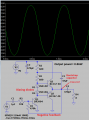
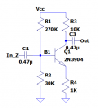
The CE now looks like this.
Waveform looks pretty good, 10 gain, and did what an inverting amplifier would do.
Problem:
However, when I now connect the 8-ohm load to the coupling capacitor, the power and voltage cross it is virtually non-existent. I assume because the impedance is too low, thus there is virtually no voltage to be absorbed available. I figured to amplify current more so:
I'm thinking of cascading an emitter follower as I researched about it and it does amplify current, I just don't know how to start designing it given it's now connected to my voltage divider. Every time I try to connect a coupling capacitor, with my previous iterations of circuit schematics, it ends up diminishing the speaker power and voltage significantly.
If cascading an emitter follower is not enough, I think a push-pull AB configuration would do? Though I suppose a darlington with emitter follower suffices.
Could you help me out trying to design this? Thank you so much.
Context:
I had a previous circuit schematic, tried it with the breadboard, didn't work because I can't seem to make the output center at 0V even with a coupling capacitor. The values I was kinda sure was the CE, anything beyond was just trial and error (I know, quite desperate and dumb); tried all sorts of topologies like push-pull (AB), darlington, and CC. And now? Just decided to start from scratch and literally try to learn on the go through no more trial and errors. So bear with me.
I need to power on the 8-ohm speaker at a max of 2W; it must deliver 1.5W. So far, the input signal would be a sinusoid at 1Khz @ 1Vpp. I chose Vcc to be 12V because I researched online that it's most optimal for this power rating; also, we shouldn't go past that point.
Steps Did:
So far, I chose to start with a CE amplifier because of its stable configuration using a voltage divider bias. We are told we have around 10K of impedance at the line level load, hence I assumed that 10K-ohm would be Rc.
I started from Rc = 10K, and moved down from designing the amplifier to have a gain of -10 because of 1Vpp approximately giving 10Vpp. Anything above the Vpp would clip the output because I assume it is due to Vswing = Vcc - Vcesat = 12 - 0.2 = 11.8? I'm still wrapping my head around this but I noticed that the output wave shifts up as gain increases and will clip at a certain point.
I then referred from G = -R3/R4=>R4 = -10K/-10 = 1K. From a tutorial online, and from me understanding KVL assuming Ic = Ie with B >= 100, Icsat = 12/(R3 + R4) = 1.09mA. From the graph of Vce and Ic, this is the region of saturation and Icq would be half of it = 545uA.
Vceq is chosen to be 6V. I would also like to know is Vceq always half of Vcc or are there any exceptions?
I learned that the current through R2 would be >= 10Ib. To be honest, I'd like to delve more into this concept but all I search online is it's recommended. Anyways R2 = B * R4 / 10= (300*1K/10) = 30K. I chose beta to be 300 because in LTSpice, the NPN model I'm using has Bf of 300. As far as I know, this is the maximum beta so I just used that and anything beyond 100 is negligible, are there any specific design choices on choosing a different beta?
R1 = VccR2 /Vb - R2
For Vbe, I looked through the datasheet and I believe it's 0.6V. So, I just made it 0.65V just to be the middle between 0.7V.
Vb = 0.65 + Ve =0.65 + 545.45u(1K) = 1.2
R1 = 12(30K)/1.2 - 30K = 270K
For the coupling capacitors, I used 1/2(pi)(lowest freq)(resistance seen by capacitor). Two things: If the frequency is fixed, will the lowest frequency just be the set frequency that is gonna be used, in this case, 1K? Is the resistance seen just Rth?
Honestly, the values I gained were quite weird as they really jacked up my wave forms, so I decided with 0.47uF for coupling even though I have no idea why this would work. I am familiar with I = C dv/dt (and we already did Laplace, ugh) but I don't have the time to see why the waves act at certain capacitor values.
I thought of putting additional capacitors like a bypass one, but until I find out how not to mess up my waves using capacitors, I wouldn't put it right now.
The CE now looks like this.
Waveform looks pretty good, 10 gain, and did what an inverting amplifier would do.
Problem:
However, when I now connect the 8-ohm load to the coupling capacitor, the power and voltage cross it is virtually non-existent. I assume because the impedance is too low, thus there is virtually no voltage to be absorbed available. I figured to amplify current more so:
I'm thinking of cascading an emitter follower as I researched about it and it does amplify current, I just don't know how to start designing it given it's now connected to my voltage divider. Every time I try to connect a coupling capacitor, with my previous iterations of circuit schematics, it ends up diminishing the speaker power and voltage significantly.
If cascading an emitter follower is not enough, I think a push-pull AB configuration would do? Though I suppose a darlington with emitter follower suffices.
Could you help me out trying to design this? Thank you so much.