Power trans.

Thread Starter

Bichrome

Joined May 2, 2014
12
We are all concerned to help here, which is why we keep questioning that the transformer itself has failed.

Denon are famous for failed thermal fuses.

https://www.google.co.uk/search?hl=...0...1ac.1.34.heirloom-hp..9.9.968.fB6XnBRc0Y4
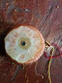
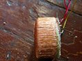
Anyway, if it is a thermal fuse than it is build inside the toroid and there is no way to unwind this transformer, at least primary winding (polyurethane everywhere).
I must admit that I was a bit too much hasty ripping things up...
 

MaxHeadRoom

Joined Jul 18, 2013
30,795
If that is 40v total, that is around 80 turns of the secondary you can see, if C.T.'d then most likely wound bi-filar.
Hopefully that is not a steel or metallic securing bolt in the centre, if so if it were to make contact with the cover it would effectively act as a shorted turn and over heat the transformer.
It could have a thermal fuse buried in the winding.
Max.
 

Thread Starter

Bichrome

Joined May 2, 2014
12
If that is 40v total, that is around 80 turns of the secondary you can see, if C.T.'d then most likely wound bi-filar.
Hopefully that is not a steel or metallic securing bolt in the centre, if so if it were to make contact with the cover it would effectively act as a shorted turn and over heat the transformer.
It could have a thermal fuse buried in the winding.
Max.
Well I don't know if there is 80 turns, but it is bi-filar and it is metallic bolt in the center and the bolt was in contact with metal case! I read about Denon thermal fuse problems and yes, there are many similar cases to mine, so i think it is burnt fuse no the transformer itself.

Transformers weight, height, width and other parameters leads to ~160VA transformer. So I think 40-0-40V with 1,87 A in each secondary would do the job.

I help so Studiot will explain about power rectifier diodes to lower rail voltages, after that I think it's good to go.
 

studiot

Joined Nov 9, 2007
4,998
±OK so here is my thinking if you need to replace the 37.5 volt transformer with a 40 volt one.

Firstly your Denon Amp is laughingly rated at 70 watts per channel into 8 ohms.

This rating is the the american typical smoke and mirrors trick with power ratings.

70 watts into 8 ohms means an rms current of 3 amps and a peak to peak voltage of 66 volts.

Taking the volts first and adding some headroom for the transistor junctions this means a rail of at least 70 volts.

Your amp has ±51 volts.

For two channels driven continuously at 70 watts this means a current draw of 6 amps plus inefficiencies.

You supply rectifiers are rated at 4 amps.

Luckily music will never drive the amp in this way.

Now you need to satisfy both current and voltage requirements.

37.5 volts RMS gives 53 volts
40 volts rms gives 56.6 volts

You reservoir capacitors see this and are rated at 56 volts, which is too close for comfort with a 40 volt transformer, even allowing for the voltage drop in the 4D4B42 bridge.

So basically you want to loose about 3 volts in each rail to return to spec.

Since the bridge has a 4 amp rating there is no point going to a higher current diode so I suggest the 5A 5100

http://www.ebay.com/itm/SR5100-5-Am...878?pt=LH_DefaultDomain_0&hash=item1e6a29278e.

The are cheap enough, and there are plenty of alternatives.

You will need 3 in series in each position you have correctly identified in red in your extract in post#18.

The 5100 is a 100 volts diode, which is more than adequate, should they ever see a reverse voltage from the rest of the circuitry.
 

Thread Starter

Bichrome

Joined May 2, 2014
12
±OK so here is my thinking if you need to replace the 37.5 volt transformer with a 40 volt one.

Firstly your Denon Amp is laughingly rated at 70 watts per channel into 8 ohms.

This rating is the the american typical smoke and mirrors trick with power ratings.

70 watts into 8 ohms means an rms current of 3 amps and a peak to peak voltage of 66 volts.

Taking the volts first and adding some headroom for the transistor junctions this means a rail of at least 70 volts.

Your amp has ±51 volts.

For two channels driven continuously at 70 watts this means a current draw of 6 amps plus inefficiencies.

You supply rectifiers are rated at 4 amps.

Luckily music will never drive the amp in this way.

Now you need to satisfy both current and voltage requirements.

37.5 volts RMS gives 53 volts
40 volts rms gives 56.6 volts

You reservoir capacitors see this and are rated at 56 volts, which is too close for comfort with a 40 volt transformer, even allowing for the voltage drop in the 4D4B42 bridge.

So basically you want to loose about 3 volts in each rail to return to spec.

Since the bridge has a 4 amp rating there is no point going to a higher current diode so I suggest the 5A 5100

http://www.ebay.com/itm/SR5100-5-Am...878?pt=LH_DefaultDomain_0&hash=item1e6a29278e.

The are cheap enough, and there are plenty of alternatives.

You will need 3 in series in each position you have correctly identified in red in your extract in post#18.

The 5100 is a 100 volts diode, which is more than adequate, should they ever see a reverse voltage from the rest of the circuitry.
Well that was eye-opening post! Thank you!
I finally got answers to all my questions!

Thank you all, I will let you know how it goes.
 

MaxHeadRoom

Joined Jul 18, 2013
30,795
and it is metallic bolt in the center and the bolt was in contact with metal case! I read about Denon thermal fuse problems and yes, there are many similar cases to mine, so i think it is burnt fuse no the transformer itself.

.
They are usually thermal fuses, so if it had the bolt connected top and bottom of the cover through the centre, then it acted as a shorted turn:eek:.
I am surprised if that was a design flaw?
Did you check ebay for toroidal? many to pick from.
Max.
 

Thread Starter

Bichrome

Joined May 2, 2014
12
They are usually thermal fuses, so if it had the bolt connected top and bottom of the cover through the centre, then it acted as a shorted turn:eek:.
I am surprised if that was a design flaw?
Did you check ebay for toroidal? many to pick from.
Max.
Bolt was connected to the upper part of the case, but not at the bottom.

Didn't check ebay, but I think it will be lot cheaper to buy it localy.

40-0-40 V 1,89 A per second wind is about 25 EUR.
 

djsfantasi

Joined Apr 11, 2010
9,237
…
So basically you want to loose about 3 volts in each rail to return to spec.

Since the bridge has a 4 amp rating there is no point going to a higher current diode so I suggest the 5A 5100

http://www.ebay.com/itm/SR5100-5-Am...878?pt=LH_DefaultDomain_0&hash=item1e6a29278e.

The are cheap enough, and there are plenty of alternatives.

You will need 3 in series in each position you have correctly identified in red in your extract in post#18.

The 5100 is a 100 volts diode, which is more than adequate, should they ever see a reverse voltage from the rest of the circuitry.
Is three in series sufficient, or would four be better?
 

studiot

Joined Nov 9, 2007
4,998
Is three in series sufficient, or would four be better?
The good old engineering compromise or split the difference.

The on voltage of many power diodes is closer to 1 volt than 0.6/0.7.
So four may to too much especially at low load.
Further, there is some safety margin in the existing circuitry.

 
Top