can I use one transformer for two power supplies, and will the grounds be connected?

Thread Starter

tsmspace

Joined Mar 16, 2026
133
I'm monkeying around with some kits. I want to make the xr2206 signal generator from jameco, which I unfortunately just used the schematic of, so technically i stole it since you can download the instructions ,,, and while wanting to build it out I kept adding "and also this" to the project.

So my plan now is to be able to plug it in, use a switch to turn on the +6-6 psu , a switch to then turn on the signal generator, and a switch to turn on a separate adjustable voltage output, made from another lm317 kit (very common kit type, but not the one with all the bonus features, just the voltage output) ,, so there will be an array of outputs to include some signal generator outputs and inputs, the outputs for the +6-6 supply, and the output for the adjustable voltage.

I want to connect them to one transformer, it's a small one at 1A. So, can't get too much power but I don't want too much power it's just a toy project. It will only be used with other little kits.

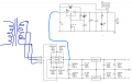
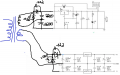
How will the ground work? I know with isolated grounds you can stack voltages like series batteries, and with shared grounds you cannot. But, in this case the grounds will be different because one will be connected to the center tap of the transformer, the other will not. Can I connect the grounds internally? Should I specifically not? Can I stack the voltages to get 24v if I want? I don't plan to , but in the event I want to try a little kit one time and it's convenient to do so, I want to know if I can. Here's a basic drawing of the plan, showing just the pasted schematics of the two supplies. plan.png
 

Ian0

Joined Aug 7, 2020
13,230
If you follow the path of the current you will find that one of the diodes in the top power supply is connected directly across the transformer secondary. You would need a transformer with two secondaries, or to remove the rectifier from the top power supply and to connect the two together at the input pins of the regulator.
 

Thread Starter

tsmspace

Joined Mar 16, 2026
133
If you follow the path of the current you will find that one of the diodes in the top power supply is connected directly across the transformer secondary. You would need a transformer with two secondaries, or to remove the rectifier from the top power supply and to connect the two together at the input pins of the regulator.
i don't know why i don't see it but I'm not seeing the diode that would be , I think you mean, shorting for half the wave? I assume you mean without any loads connected also , so just the rectifiers can't be like that, isolating just the rectifiers I should see the problem?
 

Ian0

Joined Aug 7, 2020
13,230
If you follow the path of the current you will find that one of the diodes in the top power supply is connected directly across the transformer secondary. You would need a transformer with two secondaries, or to remove the rectifier from the top power supply and to connect the two together at the input pins of the regulator.
plan.png
 

Thread Starter

tsmspace

Joined Mar 16, 2026
133
Try this instead:

View attachment 368343

You may want to make the positive side 2200uF capacitor larger, depending on how much headroom it has.
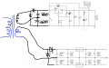
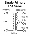
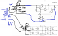
this will only give me 6v on the adjustable supply, I definitely want 12v, so I did think of this but don't like it because of that. I confess that this transformer does have 2 secondaries, although each will be only 6v. what if I do this? would I then be able to stack these to 24v if desired also?

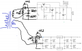
the +6-6 had these .022uf caps to filter noise across each diode of the rectifier ,, would there be any benefit to putting them across each diode as in the second picture? plan3.pngplan3.png
 
Last edited:

Ian0

Joined Aug 7, 2020
13,230
this will only give me 6v on the adjustable supply, I definitely want 12v, so I did think of this but don't like it because of that. I confess that this transformer does have 2 secondaries, although each will be only 6v. what if I do this? View attachment 368345
You've now got a voltage doubler on the adjustable supply and the same voltage on the split rail supply as you had before, just with more ripple. Keep the full bridge for the adjustable, and use what you have drawn above for the split rail, which will be perfectly fine especially if it is not supplying a lot of current.
 

Thread Starter

tsmspace

Joined Mar 16, 2026
133
You've now got a voltage doubler on the adjustable supply and the same voltage on the split rail supply as you had before, just with more ripple. Keep the full bridge for the adjustable, and use what you have drawn above for the split rail, which will be perfectly fine especially if it is not supplying a lot of current.
wouldn't my adjustable one then be left with only 6v?
 

BobTPH

Joined Jun 5, 2013
11,619
The problem with your design is that you have two separate grounds that cannot be connected together. The schematic shows both with the same ground symbol implying they are connected together. That is where the short Ian is talking about comes from.
 

Thread Starter

tsmspace

Joined Mar 16, 2026
133
The problem with your design is that you have two separate grounds that cannot be connected together. The schematic shows both with the same ground symbol implying they are connected together. That is where the short Ian is talking about comes from.
I do need to be able to connect them for sure though, since they will be in the same device and will be used on little projects like amplifier projects.

I have since changed the plan to have them each use a separate secondary, which may allow me to use the grounds? The thing is, one of them is using a negative voltage and the other is using this bottom as ground, so I don't know what that means for using them together. In some searches I see that if the secondaries are separate, then I can use them and they will count as completely independent circuits, so then even if one has ground floating in the middle and the other has ground on the common , it should still be ok to connect them they will be ok.

So I want to:
-be able to put signal generator signals into little projects powered by the adjustable power supply
- connect from-6 to +12 to get 24v (or +12 -12)
- connect +6 and +12v to the same circuit to power different sections

not that I have a particular example in mind but I just so far imagine that if I can make it now so that that's all possible I want to try.
 

Thread Starter

tsmspace

Joined Mar 16, 2026
133
Below is a sim for using a CT transformer and one bridge rectifier to get the two voltages:

The top is the full-wave bridge output, and the bottom is 1/2 the voltage.

The bottom output looks unusual as the CT uses the two grounded rectifiers as a full-wave rectifier circuit.
If you remove D1 and D2 you can better see how that works.

Note that the grounded rectifiers carry the sum of the two load currents.

The grounds for the two outputs must, of course, be common.
Is that a problem?

View attachment 368348
I need +6 and -6 for the signal generator kit, which is the basis of the project. Then, I thought I could add in a 1.5-12v adjustable output as well, making it an all-in-one ebay kit companion, so I specifically do need +6,-6 on one side, and +12 on the other.
 

B-JoJo-S

Joined Jan 3, 2026
475
The two grounds should not be connected together because one is part of a +6 , 0 , -6 source while the other is an adjustable output from n to GND. "n" being an adjustable voltage value.
 

Thread Starter

tsmspace

Joined Mar 16, 2026
133
The two grounds should not be connected together because one is part of a +6 , 0 , -6 source while the other is an adjustable output from n to GND. "n" being an adjustable voltage value.
Ok. so bear with me because if you write shorter then there's a lot of ambiguity.

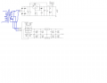
Here is the picture that represents my current plan at this point in the thread. In this picture, the n to gnd uses a voltage doubler where gnd is connected to the top secondary lead through a diode and the bottom secondary lead is just connected between the charge capacitors.

the -6 to +6 circuit has gnd connected to the bottom coil of the other secondary, and -6 is connected to the top lead of the secondary through a diode.

BUT ,, these two circuits are isolated as they are at this point connected to their own separate secondaries.

so in this form, is it still not ok to connect the grounds? Or, in the case where I want to result in +24 by stacking the voltages, I would connect GND from the n to gnd to the -6 of the -6+6 , which I could also do were they totally separate devices yes? Or, I was under the impression that because the secondaries are isolated from eachother, it WOULD be ok to do this, although because both secondaries are on a single primary, the load may easily become imbalanced if the two are placed in series, which would potentially damage the circuits. plan3.png
 

Thread Starter

tsmspace

Joined Mar 16, 2026
133
With separate secondaries, you can connect the grounds together. That is the way to go.
So do you think that running them both on voltage doublers in this way will be fine as well? I don't plan on loading them over a few hundred ma total but you can't predict the whole future.
 
Top