power supply not work

Thread Starter

kyu9971

Joined Mar 28, 2015
90
hi everyon
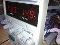
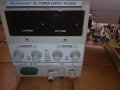
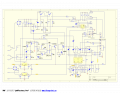
i have a problem with my bench power supply (ps 305 d)
it from today not work correctly.
the output voltage not can be regulated and is maxim value (32 volts)
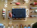
on web i found only one schematic, but is different from my board.
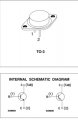
on the diagram there is an op-amp lm 324 and another ic, i think an op-amp too, while on my board there are 4 ic. two of these are lm 301 an and others two i not can see the label.
have you some ideas for solve the problem or give me some suggestions for control.
thank you so much
 

Attachments

DickCappels

Joined Aug 21, 2008
10,180
Quick suggestion:
Take the 2N3055 transistors from the back of your power supply and check them to see whether they are shorted between the collector and emitter.

This looks to be a dual power supply. Are both outputs at 30V or just one?
 
Last edited:

AlbertHall

Joined Jun 4, 2014
12,346
The 2N3055 transistors are secured with only one screw. This would probably lead to them not making good contact with the heatsink causing them to overheat and possibly leading to early failure.
 

Thread Starter

kyu9971

Joined Mar 28, 2015
90
Thank you for the suggestions.
I replaced the two 2n3055 (fortunately i had them in my home) and now the bench power supply work correctly, but i don't understand as i do to check these components.
i see the datasheet and i checked with my tester between collector and emitter and i not found short circuit.
i set up the measure instrument on "diode check".
Is there a way for to check this components?
thank you
 

Attachments

Thread Starter

kyu9971

Joined Mar 28, 2015
90
Ok, i understand.
i have 35 ohm between base and collector.
The Other 2n3055 have 70 ohm.
i think tnat these values are wrong.
the new component have an value of about 600 ohm between base and collecotor.
 

JoeJester

Joined Apr 26, 2005
4,390
If your in the diode position, the reading should be around the voltage normally associated with the particular type substance ... Silicon or germanium.

35 mV and 70 mV are closer to short than the normal 700 mV associated with silicon devices.
 

Thread Starter

kyu9971

Joined Mar 28, 2015
90
I tried a new component (2n3055).
On diode check position with read lead on base (+) and black lead on collector (-) i measured 600 mv.
if i change position of leads i measured open circuit. Should be correct since it new.
 

Attachments

DickCappels

Joined Aug 21, 2008
10,180
In the diode test position on all of the digital voltmeters I have used, you are reading millivolts rather than ohms, at a particular current.

The 2N3055 should measure around 600 millivolts for both collector-to-base and emitter-to-base. Numbers like 80 indicate a problem. When measuring the junctions in reverse they should (generally speaking) not show continuity. Often good Darlington transistors will show some resistance across the base-emitter junction.

More on testing bipolar transistors and diodes with a digital voltmeter is at the link below.

https://www.electronics-notes.com/articles/test-methods/meters/multimeter-diode-transistor-test.php
 
Top