Power Supply AC/DC OK Signal Control

Thread Starter

rennie1080

Joined Apr 10, 2017
52
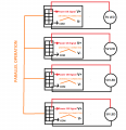
I will combine 4 ac/dc converter ( 1000W ) by using parallel operation mode to create 4kW unit. I will add 4 leds to observe converter signal health. There are digital output including POWER ON SIGNAL, AC GOOD SIGNAL and POWER OK SIGNAL. I added related piece of datasheet. I want to ask that can I use these digital outputs to drive directly 5V LED or Do I have to use a external microcontroller (like Arduino) to determine HIGH/LOW state and drive LED by usign external microcontroller(like Arduino) digital outputs? And Which of ac/dc converter digital outputs(POWER ON SIGNAL and POWER OK SIGNAL) should I use to determine that ouput dc is OK?

1602622663130.png
 

panic mode

Joined Oct 10, 2011
2,736
according to same datasheet (https://product.tdk.com/info/en/documents/instruction_manual/ac-dc-converter/cpfe1000fi_apl.pdf), page 12 tells that COM is internally connected to V-. also internal 5V is not exposed....

this means you can still add LEDs (with series resistor) between those signals and V+ because LED is supposed to draw only 10mA or so and those outputs can tolerate up to 100mA (current not a problem). also they can tolerate voltage up to 50V which is exceeding V+ in your case (so voltage is not a problem either).


something like this
1602624258903.png
 

Thread Starter

rennie1080

Joined Apr 10, 2017
52
Thank you for your answer. But I cannot understand what you mean exactly, sorry for my misunderstanding. I will add 4 Leds ( to indicate output dc of converter is OK) and make parallel 4 ac/dc converter. So If I use V+ , all leds will be parallel, that is not what I want. As you say( sorry if I misunderstood), IF I connect leds terminals by using resistor (I forget to add current limiter resistor in figure) to POWER OK SIGNAL digital pin and COM pin as figure below, does that leds will be on/off in the case of absence of output DC? Why do we connect led between V+ and PWR_OK instead of COM and PWR_OK?


Untitled.png
 

Attachments

Last edited:

Thread Starter

rennie1080

Joined Apr 10, 2017
52
So as you ( panic mode and sghioto) said, I draw a schematic that what I understand. Is what I draw is correct for that solution? 3.38 mA(if 1.8k is used as you mention and LED forward voltage is 0 assumed for the sake of example) is not enough for lighting LED, but 15.5 mA can make led light? But 3.38 mA could be enough to turn on led. How can we overcome this problem? ( If there is a missing point, can you fix me? and sorry for this questions I am newbie)

TDK LAMBDA SMPS.png
 
Last edited:

Thread Starter

rennie1080

Joined Apr 10, 2017
52
I realize that there is two different datasheet version. One of them says that PWR_OK signal is open collector output and other says that PWR_OK signal is internally connected to a 5V source via a 4.99kΩ pullup resistor. I checked from digikey and same smps in digikey have open collector output. I attached a design according to your design. Do I understand correctly?

1602664814449.png

1602665480006.png
 

sghioto

Joined Dec 31, 2017
5,388
I realize that there is two different datasheet version. One of them says that PWR_OK signal is open collector output and other says that PWR_OK signal is internally connected to a 5V source via a 4.99kΩ pullup resistor. I checked from digikey and same smps in digikey have open collector output. I attached a design according to your design. Do I understand correctly?

View attachment 219559

View attachment 219560
That is correct
 
Top