depending on RPI version and installed hardware, that draw may be anything between couple of mA to few tens of mA. for many uses that may not be suitable.
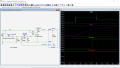
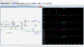
If you remove D2, the uC high output, necessary to keep M1 turned on after the button is released, now will be connected to the timing capacitor, so it will not discharge (reset) while the circuit is running.
If you remove D2, the uC high output, necessary to keep M1 turned on after the button is released, now will be connected to the timing capacitor, so it will not discharge (reset) while the circuit is running.
Yes, but that's not the condition I was describing. When the pushbutton is open *and the RPi circuit still is running*, pin 7 is high.
I interpreted "remove D2" as replacing it with a direct connection. With a wire connection there, a high at pin 7 will hold up C1 because holding up R4 will take around 1 mA, which the RPi GPIO pin can source easily. Thus, C1 cannot begin to discharge until the RPI shuts down itself. For yhe ON-Delay time to be repeatable, C1 must discharge for at least three time constants. That could be a problem for some restarts. D2 lets C1 discharge through R4 while the RPi circuit is running, so it can be fully discharged and ready for the next start cycle immediately after an RPi shutdown.
If he meant replacing it with an open circuit, then you no longer need D3.
He means replacing D2 with a wire. In order to pull the gate down through R1 and R4 when power is OFF.
I see your point but C1 will discharge rapidly through R4 and D1 when pin7 is low.
If D2 is removed how would the mosfet initially get turned ON?

 Facebook
 Google
 GitHub
 Linkedin