Power Dissipation in a simple circuit

Thread Starter

Abhinavrajan

Joined Aug 7, 2016
83
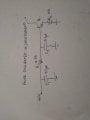
I have a transistor. And a Five Volt power supply.

The five volt supply is connected to the base of the transistor.

There are two 0.1uF capacitors and one 4.7k resistor on the line that connects the 5V to the base of the transistor.
At the base of the transistor, there's a resistor which connects the base to the ground,
And the emitter is also grounded. Open drain.

How am I supposed to calculate the value of power dissipation in each element ?
Can u please let me know how to approach this problem?
 

CEJones

Joined Feb 12, 2016
13
Nothing is switching so the capacitors ate negligible. If the transistor is open collector ( you said open drain but if it has a base it's a BJT) then the dissipation in negligible. The dissipation is through the resistors and the base emitter junction. The base emitter junction is best modelled as a diode so essentially you have 5v into a resistor into a resistor in parallel with a diode. The diode can be estimated as aproximately a 0.5V drop which tells you the power dissipation is 5V times the current through your base resistor i=v/r.
 

Tonyr1084

Joined Sep 24, 2015
7,853
5 Volts? AC or DC?

Transistor? NPN or PNP?

Transistor; is it a BJT or a FET of some sort?

Capacitors; how are they connected? I can imagine several scenarios based off of your description, and calculations on each would yield different results.

Open "Drain" - do you mean "Collector"? If your transistor has a base and an emitter then it must have a collector. And if they're "Open" - then there is no current passing through. Like Jones said, your base/emitter junction is nothing more than a diode.

Assuming you have a 5 volt Dc supply and are supplying positive current to the base of the transistor - for there to be any current flow, the transistor must be an NPN type. How and where you connect the capacitors is a mystery. If in series then you have a circuit that draws ZERO current because DC does not pass through a capacitor. If they are connecting positive to ground then they will charge up. But once charged they will not draw any more current.

Are the caps - one before the resistor to ground and the second after the resistor to ground but before the base of the transistor? You said the emitter is grounded and the drain (collector) is open. The collector is doing nothing; no current. The ONLY circuit you have going on is a 5v supply feeding a diode through a 4.7KΩ resistor.

The diode (B/E junction) will drop 0.5 volts (I always considered it to drop closer to 0.7 volts, but be that as it may, each type of transistor will have its own characteristics - a data sheet will clarify that). So your 5 volt supply is dropped by half a volt. You have essentially 4.5 volts dropping across the resistor. The capacitors and open collector have nothing to do with the circuit. It's a gold brick circuit. So what is the current through the resistor and diode junction?

Well, I = E/R. So divide your voltage by your resistance (in ohms, not K ohms) and you'll know how much current is flowing.

However, without clarification (a diagram) we can't begin to give you a "Good" answer. Answers are only as valuable as the quality of the information supplied. Sorry, the information you gave is not very clear.

5V goldbrick circuit.png
 
Last edited:

Thread Starter

Abhinavrajan

Joined Aug 7, 2016
83
5 Volts? AC or DC?

Transistor? NPN or PNP?

Transistor; is it a BJT or a FET of some sort?

Capacitors; how are they connected? I can imagine several scenarios based off of your description, and calculations on each would yield different results.

Open "Drain" - do you mean "Collector"? If your transistor has a base and an emitter then it must have a collector. And if they're "Open" - then there is no current passing through. Like Jones said, your base/emitter junction is nothing more than a diode.

Assuming you have a 5 volt Dc supply and are supplying positive current to the base of the transistor - for there to be any current flow, the transistor must be an NPN type. How and where you connect the capacitors is a mystery. If in series then you have a circuit that draws ZERO current because DC does not pass through a capacitor. If they are connecting positive to ground then they will charge up. But once charged they will not draw any more current.

Are the caps - one before the resistor to ground and the second after the resistor to ground but before the base of the transistor? You said the emitter is grounded and the drain (collector) is open. The collector is doing nothing; no current. The ONLY circuit you have going on is a 5v supply feeding a diode through a 4.7KΩ resistor.

The diode (B/E junction) will drop 0.5 volts (I always considered it to drop closer to 0.7 volts, but be that as it may, each type of transistor will have its own characteristics - a data sheet will clarify that). So your 5 volt supply is dropped by half a volt. You have essentially 4.5 volts dropping across the resistor. The capacitors and open collector have nothing to do with the circuit. It's a gold brick circuit. So what is the current through the resistor and diode junction?

Well, I = E/R. So divide your voltage by your resistance (in ohms, not K ohms) and you'll know how much current is flowing.

However, without clarification (a diagram) we can't begin to give you a "Good" answer. Answers are only as valuable as the quality of the information supplied. Sorry, the information you gave is not very clear.

View attachment 111011
Sorry. I should have uploaded a circuit diagram. Your circuit is similar to what I have mentioned expect there must be an extra 10k resistor that is between the emitter and the ground. Thank you. In the circuit that u have mentioned, what would be the power dissipation in each element including the capacitors connector to the ground? I want to know the step by step approach in solving these kind of problems. Please explain how to calculate the power dissipation in each element. Thank you!
 

AnalogKid

Joined Aug 1, 2013
10,987
Sorry. I should have uploaded a circuit diagram. Your circuit is similar to what I have mentioned expect there must be an extra 10k resistor that is between the emitter and the ground.
In post #1 you said the emitter was grounded.
Also, with nothing connected to the collector the power dissipation in the transistor will be very low. With 10 K in the emitter it will be extremely low. Are you sure that these are the only connections to the transistor?

ak
 

Thread Starter

Abhinavrajan

Joined Aug 7, 2016
83
In post #1 you said the emitter was grounded.
Also, with nothing connected to the collector the power dissipation in the transistor will be very low. With 10 K in the emitter it will be extremely low. Are you sure that these are the only connections to the transistor?

ak
Yes. The emitter is grounded with a resistor in between. How should I approach?
 

#12

Joined Nov 30, 2010
18,224
(5v-0.5v)/14700 ohms = 306.1 microamps.
5V x 306.1 ua = 1.53 milliwatts
According to the drawing in post #8 the emitter is not grounded. It is connected to a 10k resistor.
 

Tonyr1084

Joined Sep 24, 2015
7,853
OK, the 10KΩ resistor helps.

First, capacitors do not dissipate power. As for calculating this circuit - it's rather straight forward. But before I go into that lets discuss capacitors for a moment. In a DC circuit they take a charge and they give it back. They act as smoothing filters. Since you're using a +5V source chances are you don't need them. Only if your +5 is not pure, say, from a power supply would you even need them. Capacitors have a resistance of sorts. The correct term is impedance, measured in ohms. When a capacitor has no charge it also has virtually no resistance, but when it's fully charged it has virtually infinite resistance. All about circuits has a section in their forum on capacitors (in the AC portion) you might want to read to get a better understanding.

So lets ignore the presence of the capacitors, they add and take away virtually nothing. So you have a +5 volt source, a resistor, a transistor with an open collector and a 10KΩ resistor, then ground. Analog kid mentioned (5v - 0.5v) over a resistance. I'll cover the resistance in a moment, but why did he take away 0.5 volts from the equation? Well, using general terms, the NPN transistor has a 0.5 volt drop across the BE junction (Base / Emitter). So to calculate correctly what the total current is you must take into consideration this voltage drop. That's why AK used the term he did. In other words, the effective voltage of the circuit is 4.5 volts, again, using a general 0.5 volt drop for the transistor. Some transistors can have as much as 0.7 volt drop, but 0.5 will work well enough.

The next thing AK did was add up all the series resistance (the 4.7K and the 10K equals 14.7K (or 14,700Ω) total resistance). So I=E/R (current equals voltage divided by total resistance) or as AK said, (5 - 0.5) / 14700 = 0.0003061 amps. But wait - he said 306.1 µA (micro-amps). 0.001 amp is 1 milli-amp; 0.000001 is 1 micro-amp (expressed with the Mu symbol - the µ ). So the total current through the circuit IS 306.1 µA.

You asked about power dissipation on each component. Well, lets first consider the TOTAL power dissipation. Power (measured in Watts) is the product of volts times current. We know the current, so what voltage do we use? The 5v or the 4.5v? Well, since the transistor is dropping some voltage we must consider it is using up some of the power supplied by the +5v source. We don't drop the total voltage we include that as part of the total drop - or dissipation. So yes, we use the +5v. So 5 x 306.1 = 1,530.5 (somethings). Order of magnitude has ALWAYS been a problem for me, so I like to work with the numbers I got first, then move the decimal point to clarify the term correctly. Others are probably much better at it and don't need to jump through the same hoops I jump through, but I must do it this way to understand it correctly. So, 5 x 0.0003061 = 0.00153 Watts. Moving the decimal point three places gives me 1.53 mW (milli-watts, not micro-watts). If you do the absolute math you'll find AK and I both have rounded off some of the numbers. That's OK.

So you know the total amps and power dissipation for the whole circuit. Calculating the individual components shouldn't be that difficult. We KNOW the amperage flowing through the whole circuit is 0.0003061, so we can calculate the voltage drop across each component. With a current of 306.1 µA flowing through the 4.7Ω resistor we know that the voltage drop is amps times resistance. In this case I'm going to use complete numbers again (order of magnitude always screws me up), so 4700 x 0.0003061 = 1.43867 volts (let's round that off to 1.44 volts). Knowing the voltage and the current across that resistor - you multiply volts times amps for 1.44 x 0.0003061 = 0.00044 watts (or 44 mW) (that's milli-watts). The 10KΩ resistor - do the same thing with that: 10,000 x 0.0003061 = 3.061 volts. 3.061 x 0.0003061 = 0.000937 watts.

Side note about Kirchhoff's law on voltage, current and wattage; all voltages, currents and wattages for each component must add up to the total for each voltage, current or wattage. So far R1 & R2 have voltage drops equalling 1.44 volts plus 3.06 volts for a total of 4.5 volts. So that transistor is doing something after all.

Since we know the total wattage across the entire circuit, calculating how much power dissipated through the transistor should be easy enough to figure out. Wattage total = 0.00153 watts. R1 dissipates 0.00044 watts and R2 dissipates 0.000937 watts. So 0.00153 - 0.00044 - 0.000935 = 0.000153 watts remaining. Look carefully, the total wattage is 1.53 milli-watts. The wattage dissipated by Q1 is 0.153 milli-watts. They are NOT the same number. So according to Kirchhoff's law on wattage, Q1 must be dissipating 153 micro-watts, (not milliwatts) (watch out for orders of magnitude). If you take the voltage drop across Q1 (0.5 volts) and multiply that by the total current (0.0003061) you get 0.000153 watts for Q1.

No matter which way you approach it - the numbers must equal the totals. If they don't then go back and review your numbers. I certainly had to. I had to go down stairs to my lab and work this all out on my white-board.
 

AnalogKid

Joined Aug 1, 2013
10,987
The approach is to use Ohm's Law, Watt's Law, and a known fact about the physics of small signal transistors. The fact is that the base-emitter junction has the characteristics of a silicon diode, with a forward voltage (Vbe) of approximately 0.6 V. It is in series with two resistors. With Ohm's Law you can calculate the current through the series string. Once you have the current, you can use Watt's Law to calculate the power dissipated in the base-emitter diode.

ak
 

Thread Starter

Abhinavrajan

Joined Aug 7, 2016
83
OK, the 10KΩ resistor helps.

First, capacitors do not dissipate power. As for calculating this circuit - it's rather straight forward. But before I go into that lets discuss capacitors for a moment. In a DC circuit they take a charge and they give it back. They act as smoothing filters. Since you're using a +5V source chances are you don't need them. Only if your +5 is not pure, say, from a power supply would you even need them. Capacitors have a resistance of sorts. The correct term is impedance, measured in ohms. When a capacitor has no charge it also has virtually no resistance, but when it's fully charged it has virtually infinite resistance. All about circuits has a section in their forum on capacitors (in the AC portion) you might want to read to get a better understanding.

So lets ignore the presence of the capacitors, they add and take away virtually nothing. So you have a +5 volt source, a resistor, a transistor with an open collector and a 10KΩ resistor, then ground. Analog kid mentioned (5v - 0.5v) over a resistance. I'll cover the resistance in a moment, but why did he take away 0.5 volts from the equation? Well, using general terms, the NPN transistor has a 0.5 volt drop across the BE junction (Base / Emitter). So to calculate correctly what the total current is you must take into consideration this voltage drop. That's why AK used the term he did. In other words, the effective voltage of the circuit is 4.5 volts, again, using a general 0.5 volt drop for the transistor. Some transistors can have as much as 0.7 volt drop, but 0.5 will work well enough.

The next thing AK did was add up all the series resistance (the 4.7K and the 10K equals 14.7K (or 14,700Ω) total resistance). So I=E/R (current equals voltage divided by total resistance) or as AK said, (5 - 0.5) / 14700 = 0.0003061 amps. But wait - he said 306.1 µA (micro-amps). 0.001 amp is 1 milli-amp; 0.000001 is 1 micro-amp (expressed with the Mu symbol - the µ ). So the total current through the circuit IS 306.1 µA.

You asked about power dissipation on each component. Well, lets first consider the TOTAL power dissipation. Power (measured in Watts) is the product of volts times current. We know the current, so what voltage do we use? The 5v or the 4.5v? Well, since the transistor is dropping some voltage we must consider it is using up some of the power supplied by the +5v source. We don't drop the total voltage we include that as part of the total drop - or dissipation. So yes, we use the +5v. So 5 x 306.1 = 1,530.5 (somethings). Order of magnitude has ALWAYS been a problem for me, so I like to work with the numbers I got first, then move the decimal point to clarify the term correctly. Others are probably much better at it and don't need to jump through the same hoops I jump through, but I must do it this way to understand it correctly. So, 5 x 0.0003061 = 0.00153 Watts. Moving the decimal point three places gives me 1.53 mW (milli-watts, not micro-watts). If you do the absolute math you'll find AK and I both have rounded off some of the numbers. That's OK.

So you know the total amps and power dissipation for the whole circuit. Calculating the individual components shouldn't be that difficult. We KNOW the amperage flowing through the whole circuit is 0.0003061, so we can calculate the voltage drop across each component. With a current of 306.1 µA flowing through the 4.7Ω resistor we know that the voltage drop is amps times resistance. In this case I'm going to use complete numbers again (order of magnitude always screws me up), so 4700 x 0.0003061 = 1.43867 volts (let's round that off to 1.44 volts). Knowing the voltage and the current across that resistor - you multiply volts times amps for 1.44 x 0.0003061 = 0.00044 watts (or 44 mW) (that's milli-watts). The 10KΩ resistor - do the same thing with that: 10,000 x 0.0003061 = 3.061 volts. 3.061 x 0.0003061 = 0.000937 watts.

Side note about Kirchhoff's law on voltage, current and wattage; all voltages, currents and wattages for each component must add up to the total for each voltage, current or wattage. So far R1 & R2 have voltage drops equalling 1.44 volts plus 3.06 volts for a total of 4.5 volts. So that transistor is doing something after all.

Since we know the total wattage across the entire circuit, calculating how much power dissipated through the transistor should be easy enough to figure out. Wattage total = 0.00153 watts. R1 dissipates 0.00044 watts and R2 dissipates 0.000937 watts. So 0.00153 - 0.00044 - 0.000935 = 0.000153 watts remaining. Look carefully, the total wattage is 1.53 milli-watts. The wattage dissipated by Q1 is 0.153 milli-watts. They are NOT the same number. So according to Kirchhoff's law on wattage, Q1 must be dissipating 153 micro-watts, (not milliwatts) (watch out for orders of magnitude). If you take the voltage drop across Q1 (0.5 volts) and multiply that by the total current (0.0003061) you get 0.000153 watts for Q1.

No matter which way you approach it - the numbers must equal the totals. If they don't then go back and review your numbers. I certainly had to. I had to go down stairs to my lab and work this all out on my white-board.
Whoa! A superb explanation. Simply brilliant. I understood every single word mentioned by you. I am sure I will never forget the steps given any other different circuit! Thank you so much! Please help me in future as well.
 

Thread Starter

Abhinavrajan

Joined Aug 7, 2016
83
OK, the 10KΩ resistor helps.

First, capacitors do not dissipate power. As for calculating this circuit - it's rather straight forward. But before I go into that lets discuss capacitors for a moment. In a DC circuit they take a charge and they give it back. They act as smoothing filters. Since you're using a +5V source chances are you don't need them. Only if your +5 is not pure, say, from a power supply would you even need them. Capacitors have a resistance of sorts. The correct term is impedance, measured in ohms. When a capacitor has no charge it also has virtually no resistance, but when it's fully charged it has virtually infinite resistance. All about circuits has a section in their forum on capacitors (in the AC portion) you might want to read to get a better understanding.

So lets ignore the presence of the capacitors, they add and take away virtually nothing. So you have a +5 volt source, a resistor, a transistor with an open collector and a 10KΩ resistor, then ground. Analog kid mentioned (5v - 0.5v) over a resistance. I'll cover the resistance in a moment, but why did he take away 0.5 volts from the equation? Well, using general terms, the NPN transistor has a 0.5 volt drop across the BE junction (Base / Emitter). So to calculate correctly what the total current is you must take into consideration this voltage drop. That's why AK used the term he did. In other words, the effective voltage of the circuit is 4.5 volts, again, using a general 0.5 volt drop for the transistor. Some transistors can have as much as 0.7 volt drop, but 0.5 will work well enough.

The next thing AK did was add up all the series resistance (the 4.7K and the 10K equals 14.7K (or 14,700Ω) total resistance). So I=E/R (current equals voltage divided by total resistance) or as AK said, (5 - 0.5) / 14700 = 0.0003061 amps. But wait - he said 306.1 µA (micro-amps). 0.001 amp is 1 milli-amp; 0.000001 is 1 micro-amp (expressed with the Mu symbol - the µ ). So the total current through the circuit IS 306.1 µA.

You asked about power dissipation on each component. Well, lets first consider the TOTAL power dissipation. Power (measured in Watts) is the product of volts times current. We know the current, so what voltage do we use? The 5v or the 4.5v? Well, since the transistor is dropping some voltage we must consider it is using up some of the power supplied by the +5v source. We don't drop the total voltage we include that as part of the total drop - or dissipation. So yes, we use the +5v. So 5 x 306.1 = 1,530.5 (somethings). Order of magnitude has ALWAYS been a problem for me, so I like to work with the numbers I got first, then move the decimal point to clarify the term correctly. Others are probably much better at it and don't need to jump through the same hoops I jump through, but I must do it this way to understand it correctly. So, 5 x 0.0003061 = 0.00153 Watts. Moving the decimal point three places gives me 1.53 mW (milli-watts, not micro-watts). If you do the absolute math you'll find AK and I both have rounded off some of the numbers. That's OK.

So you know the total amps and power dissipation for the whole circuit. Calculating the individual components shouldn't be that difficult. We KNOW the amperage flowing through the whole circuit is 0.0003061, so we can calculate the voltage drop across each component. With a current of 306.1 µA flowing through the 4.7Ω resistor we know that the voltage drop is amps times resistance. In this case I'm going to use complete numbers again (order of magnitude always screws me up), so 4700 x 0.0003061 = 1.43867 volts (let's round that off to 1.44 volts). Knowing the voltage and the current across that resistor - you multiply volts times amps for 1.44 x 0.0003061 = 0.00044 watts (or 44 mW) (that's milli-watts). The 10KΩ resistor - do the same thing with that: 10,000 x 0.0003061 = 3.061 volts. 3.061 x 0.0003061 = 0.000937 watts.

Side note about Kirchhoff's law on voltage, current and wattage; all voltages, currents and wattages for each component must add up to the total for each voltage, current or wattage. So far R1 & R2 have voltage drops equalling 1.44 volts plus 3.06 volts for a total of 4.5 volts. So that transistor is doing something after all.

Since we know the total wattage across the entire circuit, calculating how much power dissipated through the transistor should be easy enough to figure out. Wattage total = 0.00153 watts. R1 dissipates 0.00044 watts and R2 dissipates 0.000937 watts. So 0.00153 - 0.00044 - 0.000935 = 0.000153 watts remaining. Look carefully, the total wattage is 1.53 milli-watts. The wattage dissipated by Q1 is 0.153 milli-watts. They are NOT the same number. So according to Kirchhoff's law on wattage, Q1 must be dissipating 153 micro-watts, (not milliwatts) (watch out for orders of magnitude). If you take the voltage drop across Q1 (0.5 volts) and multiply that by the total current (0.0003061) you get 0.000153 watts for Q1.

No matter which way you approach it - the numbers must equal the totals. If they don't then go back and review your numbers. I certainly had to. I had to go down stairs to my lab and work this all out on my white-board.

So, capacitors never dissipate power even if they are connected in an AC circuit ?
Under what situations or circumstances do capacitors dissipate power ?
 

Tonyr1084

Joined Sep 24, 2015
7,853
They don't dissipate power. Anything that gets HOT is dissipating power. Coils generally don't dissipate power either. Though they do some strange things in a circuit. Worth reading both capacitors AND inductors.

In an AC circuit they act like resistors at certain frequencies and like short circuits at others. So much to learn about them it's best if you read a published article on the matter. I'm still learning too. In fact, I've had to read those sections a couple of times before things began to stick. Just how stuck they are - time will tell (if I don't forget them).
 

Thread Starter

Abhinavrajan

Joined Aug 7, 2016
83
They don't dissipate power. Anything that gets HOT is dissipating power. Coils generally don't dissipate power either. Though they do some strange things in a circuit. Worth reading both capacitors AND inductors.

In an AC circuit they act like resistors at certain frequencies and like short circuits at others. So much to learn about them it's best if you read a published article on the matter. I'm still learning too. In fact, I've had to read those sections a couple of times before things began to stick. Just how stuck they are - time will tell (if I don't forget them).
Sure. I am just a beginner. Learning all the basics and getting it right. Self-paced learning.
You said,"Anything that gets hot is dissipating power"
So, you are implying that capacitors and inductors don't heat up as they don't dissipate any power?
 

wayneh

Joined Sep 9, 2010
17,496
So, capacitors never dissipate power even if they are connected in an AC circuit ?
Ideally no, but no component is ideal. Capacitor's do have an equivalent series resistance, ESR, that can cause heating under conditions of high frequency charging and discharging of the capacitor, leading to a high average current. This is a big deal in, for instance, switch mode power supplies. But even there, it's a small fraction of the total power. For most DIY hobby circuits, power dissipation in the capacitors is negligible. They don't get hot.
 

#12

Joined Nov 30, 2010
18,224
Equivalent series resistance exists, so does dissipation factor, but these are very minor at low frequencies.
For instance, I can connect a 10 uf 370V oil filled capacitor directly to a 240 volt 60 Hz power line and leave it for an hour. It will not be hot when I return. On the other hand, I can install an ancient paper and wax capacitor in a guitar amplifier and a brilliant musician can tell the difference in the sound. Switching power supplies present a very real challenge in trying to avoid overheating the electrolytic capacitors because the capacitors experience whole amps being switched in and out at kilohertz frequencies. There are circuits where tiny differences from "ideal" are a serious problem to be considered, and there are circuits where these tiny deviations make no detectable difference.
 
Top