Facebook
 Google
 GitHub
 Linkedin
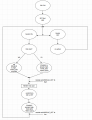
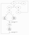
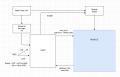
I need to design a smart logic without any MCU and relays that would do this :
1/ When main power 24V is ON and the switch is in OFF -> no action.
2/ When main power 24V is ON and the switch is in ON -> enable the module power and no pulse on PWR_BTN. Module power needs to stay enable until 24V is powered on. When the switch is then switched from ON to OFF - PWR_BTN pulse needs to be generated, the same if the switch goes from OFF to ON again. Enable has to stay active during these actions until 24V is ON.
3/ When main power 24V is OFF and the switch is in ON position and then main power 24V goes ON, this has to cause ENABLE module active but no PWR_BTN pulse. PWR_BTN pulse has to be generated once the switch is then switched from ON to OFF and 24V remains ON, also when again the switch goes from OFF to ON again and 24V still remains ON.
Module has autostart, which means PWR_BTN pulse can not be generated when 24V is ON and you switch the switch from OFF to ON for the first time and the same if the switch is in ON position and you plugged 24V in. This two actions will just enable the module power.
Module_off signal is low if the module is in off state (when powered!) and module power remains active until 24V is ON.
Does anyone have an idea how to do that correctly?
Thanks.
Attachments
-
 84 KB Views: 27
 -
 37.6 KB Views: 26