Positive/Negative Wave generator using a 555

Thread Starter

Mike9104

Joined Sep 23, 2018
5
Hello all,

I need a circuit that will reverse the voltage applied to a small coil with a variable duty cycle, nominally 1s. The intended input is 9VDC.

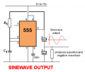
The only circuit I found to accomplish this with a 555 is attached. The problem is that values for R1, C1, and the output caps are not included, so I was hoping someone had a similar schematic with values, or accompanying lookup table w/values for a range of output characteristics.

Thank you!
Mike
 

Attachments

AlbertHall

Joined Jun 4, 2014
12,345
That circuit will only make a square wave. Is it a sinewave that you need?
What details of the coil can you give - resitance, inductance?
 

crutschow

Joined Mar 14, 2008
34,285
I need a circuit that will reverse the voltage applied to a small coil with a variable duty cycle, nominally 1s. The intended input is 9VDC.
Do you mean you want the voltage reversed at one second intervals?
Do you want +9V and then -9V applied to the coil?

If so, you could do that with a 555 timer, a flip-flop, and a MOSFET bridge.
 

Thread Starter

Mike9104

Joined Sep 23, 2018
5
Hi Zapper - Yes to exactly what you said. I need the voltage to the coil to reverse, going from +9VDC to -9VDC every second (variable using variable resistors). I think a square wave would be best but I believe a sine wave would work as well. This is for a very simple electro-mechanical function, whereby an arm with a fixed magnet will be made to swing back and forth as it is pulled and repelled by this coil. Thanks for your reply!
 

crutschow

Joined Mar 14, 2008
34,285
I think a square wave would be best but I believe a sine wave would work as well.
You said variable duty-cycle in your first post.
Do you just mean variable frequency?
his is for a very simple electro-mechanical function, whereby an arm with a fixed magnet will be made to swing back and forth as it is pulled and repelled by this coil.
Sounds like a pendulum for a clock.
 

Thread Starter

Mike9104

Joined Sep 23, 2018
5
That circuit will only make a square wave. Is it a sinewave that you need?
What details of the coil can you give - resitance, inductance?
Hi AlbertHall - This circuit is admittedly very imprecise, I wrapped 500 turns of 28AWG wire on a plastic spool and applied 9VDC. The energized coil is working perfectly to repel/attract a fixed magnet attached to an arm. I need to alternate the polarity in order to make the arm swing. I haven't measured/calculated the resistance or inductance as it doesn't need to be precise. Now that I have proven that the coil will do the job, I just need a circuit to drive the voltage up and down at the right interval. I expect to need a transistor to handle the coil current. Thanks for your reply!
 

Thread Starter

Mike9104

Joined Sep 23, 2018
5
You said variable duty-cycle in your first post.
Do you just mean variable frequency?

Sounds like a pendulum for a clock.
You are correct, variable frequency. I need to be able to tune the voltage fluctuation from + to - to get the timing of the arm correct. It can definitely be thought of as similar to a clock pendulum; this is for a proof of concept for an industrial application, ultimately an engineering firm will optimize the design. Thanks.
 

Thread Starter

Mike9104

Joined Sep 23, 2018
5
So what is the coil resistance or its current?
Hi cruts
Tell us the diameter of the spool and we can make a good estimate of the rest.
Thanks AlbertHall! I attached three photos. The center of the spool is 1/16"D. The spool itself is 1.5"D, but the 500 turns reach the 1.25"D. The height of the coil is 3/8".

I hope this is enough info, I really appreciate interest and help!
 

Attachments

crutschow

Joined Mar 14, 2008
34,285
Here's the LTspice simulation of a circuit that supplies alternating polarity, quarter second pulses to the coil with a 1 second period.
Or do you want 1 second between alternating pulses, and/or higher duty-cycle pulses?

Edit: Incorrect circuit removed.
Back to the drawing board. (See post #18). o_O
 
Last edited:

AlbertHall

Joined Jun 4, 2014
12,345
Here's the LTspice simulation of a circuit that supplies alternating polarity, quarter second pulses to the coil with a 1 second period.
Is this right?
M3 and M4 are switched on and off together. If M1 or M2 is switched on while M3 and M4 are both switched on there will be a very high current, effectively a short circuit, through the conducting side.
 
Top