PNP Switch Issue

ErnieM

Joined Apr 24, 2011
8,415
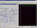
Crusts how nailed it. To prove it, lok at the voltage where the transistor meets the resistor. You should see the same voltage tail there. That indicates there is no "large" current flowing into the LED.

Another thing to prove this effect is to swap the resistor and LED so the resistor becomes a direct read of the current. That voltage will tail off much faster.
 

Bordodynov

Joined May 20, 2015
3,431
Use additional resistor Rbe = 300 ohms. What is the supply voltage of the microcontroller? I will try to create a model of your desired diode. I'll do it on Monday. Now I can only use the phone.
 

DickCappels

Joined Aug 21, 2008
10,661
Did anybody notice Bordodynow's soution in post #4?
@Bordodynov

There is no load on the collector/drain once the voltage falls below about 1 volt because the LED is between the collector/drain and ground.
 

Thread Starter

Gord11

Joined Nov 27, 2015
14
Use additional resistor Rbe = 300 ohms. What is the supply voltage of the microcontroller? I will try to create a model of your desired diode. I'll do it on Monday. Now I can only use the phone.

Hello Bordodynov,

The micorcontroller voltage is also running at the 5V, so just a normal 5V output pin.

Thank you,
 

Thread Starter

Gord11

Joined Nov 27, 2015
14
Did anybody notice Bordodynow's soution in post #4?
@Bordodynov

There is no load on the collector/drain once the voltage falls below about 1 volt because the LED is between the collector/drain and ground.

Hello DickCappels,

I am a little confused by this - does this mean that it is not due to charge storage, just the forward voltage of the LED? If so, why does the operating frequency have an effect.
 

Thread Starter

Gord11

Joined Nov 27, 2015
14
Actually i think that i can now see the reason that the frequency has an effect, perhaps if i look closer at the wave form when operating manually, i would see that last 1V tailing off, but when operating at 38Khz the scope makes it clearer, less time for the tail to dissipate.

I hope i am understanding this correctly.
 

DickCappels

Joined Aug 21, 2008
10,661
Try the circuit modification in Post #4 (schematic on the right) and I think you will understand.

If it is of any comfort, the LED is off by the time the voltage reaches about 1 volt.
 

Bordodynov

Joined May 20, 2015
3,431
Pay attention to the blue line v (X) post # 4. This voltage across the diode. I thought that there was emitted signal, not the voltage across the diode. So I do not really use a great option tt = 5uS. Put the LED parallel resistor and you will be happy.
 
Top