Plug & Play or Go Shopping?

Thread Starter

David916

Joined Sep 29, 2018
9
Hello all!

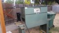
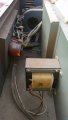
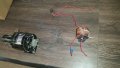
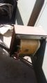
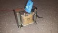
I have a Fractional Horsepower Gear Motor that I took out of a non-working heat shrink tunnel. It has two blue wires and two black wires.

Can it be wired to a 110v outlet as is, and if so, how should I connect the motor wires to a black, white, and green?

Or, do I need a run capacitor or some other extra parts and if so, what should I buy?

Specs:
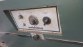
Bodine Electric Company
Model: NSH-34RH
110V
1 Phase
75 Amps
1/15 HP
58 RPM

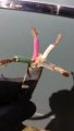
Attached is a wiring diagram Bodine emailed me. I'm a new mechatronics student and don't know how to read electrical schematics just yet. If anyone needs a hand with pneumatics, I am more than happy to lend a hand.

Any help is much appreciated.

Thank you,
David
 

Attachments

shortbus

Joined Sep 30, 2009
10,045
Two questions for you,
1. do you have the controller that is shown in the schematic?
2. does your motor have 4 wires or only two?

The Bodine site doesn't seem to list these motors by model, but instead uses serial numbers for reference. so what is the serial number to get the data sheet for the motor.
 

MaxHeadRoom

Joined Jul 18, 2013
28,617
I think that was meant to be 0.75amps?
That motor could be a shaded pole version, if so it does not need a cap.
But if bi-directional then needs a cap, looks like this one?


Max.
 

Thread Starter

David916

Joined Sep 29, 2018
9
Shortbus:
1) 4 wires, 2 black 2 blue.
2) I have a speed controller. I still have the heat shrink machine and just took some pictures. It looks like the machine comes with a gear motor, blower, and heater along with it's controllers. I can remove all the parts, clean them, and put up pictures if it helps?

Bill B:
The label is pretty scratched up. May be .75, sorry.

MaxHeadRoom:
Yep, that's the one!

Pictures:
1. Front exterior
2. Front interior
3. Rear exterior
4. Rear interior
 

Attachments

LesJones

Joined Jan 8, 2017
4,174
Are there any bridge rectifiers in the unit ? Bodine seem to make quite a lot of shunt wound (DC) motors that could have the speed controlled by varying the armature voltage and keeping the field voltage fixed. The thing against this theory is that the motor is marked 1 phase.

Les.
 
Last edited:

Thread Starter

David916

Joined Sep 29, 2018
9
Ok, I'm back with some more pictures and insight.

Yep, they put 2 bridge rectifiers. The speed controller has 3 red wires and 1 white which was grounded to the unit. 1 Red goes to a black rectifier, one Red to a silver rectifier, and the other Red goes to a transformer. Is the transformer one going to be an issue? I've attached a picture of the transformer and black and silver rectifiers (I'm holding the black one but the silver one is right behind it in the picture)

When I disconnected it a long time ago there was a Black, Red, White, and Green wire from the plug that connected to the 2 black and 2 blue wires to the motor. I can't remember how to connect them but since I've taken the entire unit apart and only need the motor and controller, there may be another configuration?

Looking at the motor again I can't verify that it is 1 phase. I tried putting a paint pen on the plate and lightly sanding the surface to expose the damaged engraving but it's beyond recognition..
 

Attachments

LesJones

Joined Jan 8, 2017
4,174
Looking on the web for this motor suggests that it is DC. Here are 4 links I found.

https://www.radwell.co.uk/en-GB/Buy/BODINE ELECTRIC/NSH34RH?redirect=true

https://gcplastics.com/motors/bodine-nsh-34rh-115hp-motor

https://www.imssupply.com/catalog/bodine-electric/nsh-34rh.html

http://bodine-electric.industrialpartner.com/products-n/nsh34rh.htm

I think you will find that the motor has brushes and the resistance between one pair of wires is much higher than the resistance between the other pair. The high resistance pair is the field.

Les.
 

Thread Starter

David916

Joined Sep 29, 2018
9
Thank you Les for taking the time.

I feel silly because next to HZ on the motor it says DC. Also, the heat shrink tunnel machine is 240v and it looks like the power gets reduced before getting to the 2 blowers and motor.

OOOh boy. So I take it I can't wire up just the gear motor to AC with the rectifiers, speed controller, and transformer?

Dave.
 

LesJones

Joined Jan 8, 2017
4,174
I have seen some speed controllers that have a supply for the field winding that is just the rectified supply from the transformer (Or mains if it is the correct voltage.) The speed is then controlled by varying the duty cycle of a PWM waveform or by changing the coductin ange of SCRs in a rectifier circuit. In your machine I expect to find two bridge rectifiers, One directly from the AC supply frrding the field and one fed from the output of the variac which feeds the armature, Your profile does not say which country you are in so we don't know what your mains voltage is. If it is 110 volts then a transformer will not be needed.

Les.
 

MaxHeadRoom

Joined Jul 18, 2013
28,617
If the field is being varied to control the rpm, the torque capability will drop as the speed is increased.
It looks that whatever is controlled is done with a variac before the bridge rectifiers.
Max.
 

Thread Starter

David916

Joined Sep 29, 2018
9
Removed everything inside the machine and laid it out on the floor just as it were.

My new questions is:

The unit has another large motor (blower) and another small one, heater core, and the DC gear reduction motor that I'd like to use -that's quite a bit of power draw. The heat shrink tunnel hooks up to a 220v outlet to power all the devices. Since I do not need all of the other units, can I bypass the transformer and power it straight to 110v? I ask because on one side of the transformer it reads 220 and the other reads 110v. This motor is hooked up to the 110v side so since the rectifiers do the job of making this DC motor work on 110v, can I bypass the transformer and plug it straight into the wall? The red wire on the 110v side of the transformer is positive and the white was bolted on the sheet metal and is negative.

I attached a picture of the entire layout for this unit, minus the 220v wires that come into the other side of the transformer. It starts with the transformer, then a fuse, then the speed controller, then 2 rectifiers, then motor.

My short time on this forum and tearing this down has taught me more then I ever knew. Really forward to advancing in mechatronics and learning about electronics.

Thanks again!
 

Attachments

MaxHeadRoom

Joined Jul 18, 2013
28,617
I 120v rated then you can power direct from a 120v wall outlet, for just the motor.
One bridge is for the field, the other for the armature, measure the resistance, the field should be higher resistance than the armature, you can't back feed/rotate the motor to tell this way because it looks like a worm-pinion reduction.
Make sure you include the fuse and the earth GND conductor.
Max.
 

Thread Starter

David916

Joined Sep 29, 2018
9
Thank you.

One final thing, the transformer, fuse, rectifiers, and speed controller were housed inside the unit and the gear reduction motor was located outside. Therefore, the manufacturer wired an outlet so the gear reduction motor can be plugged in from the outside of the unit to access the wires inside. Since I do not need the outlet and cable I can remove them. Before I remove the 4 wires from the outlet, I noticed two of them are on a side that has a negative symbol and the other two are on the other side with no markings.

How would I be able to tell how to wire the 4 blue wires coming from the two rectifiers to the 2 blue and 2 black going into the motor?
 

Attachments

Top