Please help with solving these circuits

Thread Starter

Site

Joined Sep 3, 2017
15
I have been out of school for almost 4 years and I realized the hard way that I am a little bit Rusty on these.

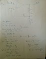
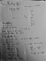
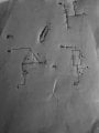
I think I was able to solve #1 by redrawing the circuit and using a common method that is used to solve a typical wheatstone Bridge Circuit.

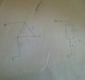
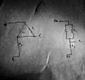
For #2 I am really having a hard time to redraw the circuit. I am not sure if I should draw a wire from V1 directly to the ground and then apply nodal analysis or if I should use another method that I am not aware of. I tried that and I ended up with 2 unknown and 1 equation.

I am also not sure that to interpret circuit diagrams where some nodes are just left hanging in the air like V1 in problem #2, and #3.

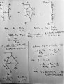
I totally have no idea where to start on #3 and on #4 so please help me understand these Circuits.

I really appreciate your help.

Thank you very much
 

Attachments

MrChips

Joined Oct 2, 2009
30,720
For #1, you have two methods of solving this. You can use Kirchoff's voltage and current laws and then do the loop analysis.
Or you can reduce resistances in series and parallel to a single resistance and use Ohm's Law.

For #2, V1 is not connected to anything and hence the net equivalent of R3 is infinite resistance. Start from there.

For #3, assume that the voltage at pin-6 is the same as that at pin-7. Also the assignment states that no current flows into V+ and V- input pins.
Hence Rs does not appear in the answer.

For #4, the voltage across a capacitor charging or discharging is a differential equation. Do you know how to work with differential equations?
 

Thread Starter

Site

Joined Sep 3, 2017
15
For #1, you have two methods of solving this. You can use Kirchoff's voltage and current laws and then do the loop analysis.
Or you can reduce resistances in series and parallel to a single resistance and use Ohm's Law.

For #2, V1 is not connected to anything and hence the net equivalent of R3 is infinite resistance. Start from there.

For #3, assume that the voltage at pin-6 is the same as that at pin-7. Also the assignment states that no current flows into V+ and V- input pins.
Hence Rs does not appear in the answer.

For #4, the voltage across a capacitor charging or discharging is a differential equation. Do you know how to work with differential equations?

Thank you very much for your answer Sir. I believe what I am having the most difficulty with is the fact that some of the nodes like V1 in #2 and #3 are hanging. Therefore it gives me the impression that it is an open circuit but then I know that is not true.

For #3, when you say that the net equivalent resistance of R3 is infinite, does that mean that no current is flowing through R3 therefore the voltage across R3 is 0.

Yes I am familiar with differential equations Sir.
 

MrChips

Joined Oct 2, 2009
30,720
Thank you very much for your answer Sir. I believe what I am having the most difficulty with is the fact that some of the nodes like V1 in #2 and #3 are hanging. Therefore it gives me the impression that it is an open circuit but then I know that is not true.

For #3, when you say that the net equivalent resistance of R3 is infinite, does that mean that no current is flowing through R3 therefore the voltage across R3 is 0.

Yes I am familiar with differential equations Sir.
For #2, no current is flowing in R3.
 

Thread Starter

Site

Joined Sep 3, 2017
15
Also for #2 when it says find V1 with respect to the ground, does that mean that V1 = V(R4) + V(R3) and since V(R3) is 0 so V1= V(R4).
 

Thread Starter

Site

Joined Sep 3, 2017
15
Also, since there only an empty horizontal wire connecting the R2 to R3, can I conclude that they are in parallel and combine them to find the voltage across the combination and set it equal to V1.

Thank you again Mr. C
For #2, no current is flowing in R3.
Also, since there only an empty horizontal wire connecting the R2 to R4, can I conclude that they are in parallel and combine them to find the voltage across the combination and set it equal to V1.

Thank you again.
 

Thread Starter

Site

Joined Sep 3, 2017
15
For #1, you have two methods of solving this. You can use Kirchoff's voltage and current laws and then do the loop analysis.
Or you can reduce resistances in series and parallel to a single resistance and use Ohm's Law.

For #2, V1 is not connected to anything and hence the net equivalent of R3 is infinite resistance. Start from there.

For #3, assume that the voltage at pin-6 is the same as that at pin-7. Also the assignment states that no current flows into V+ and V- input pins.
Hence Rs does not appear in the answer.

For #4, the voltage across a capacitor charging or discharging is a differential equation. Do you know how to work with differential equations?
For #4, I am still a bit confused sir.
What does is mean that V1 is at Vdd at t=0.
Is the capacitor initially charges or is it initially discharge.
Will it make sense to redraw the circuit as I uploaded.

Thank you for your help in answering all my questions.
 

Attachments

WBahn

Joined Mar 31, 2012
29,979
Also, since there only an empty horizontal wire connecting the R2 to R3, can I conclude that they are in parallel and combine them to find the voltage across the combination and set it equal to V1.

Thank you again Mr. C


Also, since there only an empty horizontal wire connecting the R2 to R4, can I conclude that they are in parallel and combine them to find the voltage across the combination and set it equal to V1.

Thank you again.
Which of the four problems are you talking about? This is why we strongly encourage a one-problem-per-thread approach. What more than one problem is involved, the responses invariably start getting chaotic and difficult to sort out.

Assuming you are talking about Problem #2 for both of these, R2 and R3 are NOT in parallel. Always keep the fundamentals in mind. Two components are in parallel when they are connected to the same nodes. The horizontal wire connects one side of R2 and R3 to be the same, but the other end of R2 is tied to the reference (ground) node while the other side of R3 is tied to V1. So unless V1 is tied to 0 V, they are not in parallel.

Similarly, R2 and R4 ARE in parallel because they satisfy the requirement they be connected to the same two nodes.
 

WBahn

Joined Mar 31, 2012
29,979
This is my attempt to solve #3
I have a hard time reading your work (the image is too blurry for me), but it appears you are completely ignoring the key factor they want you to look at, which is that the opamp only has finite gain. The 'A' in the problem is the finite open-loop gain of the opamp. The 'A' in your answer is the closed-loop gain of the opamp circuit assuming that the open-loop gain of the opamp is infinite.
 

WBahn

Joined Mar 31, 2012
29,979
For #4, I am still a bit confused sir.
What does is mean that V1 is at Vdd at t=0.
Is the capacitor initially charges or is it initially discharge.
Will it make sense to redraw the circuit as I uploaded.

Thank you for your help in answering all my questions.
They are saying that, somehow, the voltage at V1 happens to be equal to Vdd at a particular moment in time. The easiest way to visualize it is that there is a switch between V1 and Vdd that has been closed for a long time (a "long time" meaning that everything has had time to reach steady state). Then, at t=0, the switch is opened and the circuit, as shown, is allowed to respond.
 

bertus

Joined Apr 5, 2008
22,270
Hello,

@WBahn , I played a bit with the saturation and levels of the pictures in the GIMP.
I hope they are better readable like this:

site_1_IMG_20170903_103605~01_corr.jpg

site_2_IMG_20170903_112440~01_corr.jpg

site_3_IMG_20170903_120757~01_corr.jpg

Bertus
 

WBahn

Joined Mar 31, 2012
29,979
@bertus : That definitely helps. The opamp one is still blurry enough to make it hard (for me) to see all the details, but the mistake in the setup is obvious.

@Site: In Problem #3 you say, "From Problem" (or at least that's what I think it says) i+ = i- = 0. That's fine, because the problem certainly does mean that when it says that no current flows into V+ or V-. But then you say that V+ = V-. The problem most certainly does NOT say that! In fact, it very explicitly states that Vout = A(V+ - V-). If V+ = V-, then Vout must be identically zero!
 

Thread Starter

Site

Joined Sep 3, 2017
15
@bertus, thank you very much
@WBahn , thank very much as well.

For #1, I redrew the circuit so that it would look like an unbalanced wheatstone Bridge problem. (R1//R2) in series with (R3//R4) and then used KVL to find the current. I have attached the picture of my work but not sure if it is correct.

For #2, I learned that R3 is not connected to anything. Therefore, I set (R2//R4) in series with R1 and then used voltage divider to get the voltage V1 which is the same as the voltage across (R2//R4). I have also attached my work but I don't know if that is correct either.

For #3, I thought I would use the fact that for all opAmp, V+=V- but you pointed out that Vout = A(V+ - V-) would not be true. I will try again and see.

For #4, I am still really lost on how to start the problem
 

Attachments

Thread Starter

Site

Joined Sep 3, 2017
15
@bertus : That definitely helps. The opamp one is still blurry enough to make it hard (for me) to see all the details, but the mistake in the setup is obvious.

@Site: In Problem #3 you say, "From Problem" (or at least that's what I think it says) i+ = i- = 0. That's fine, because the problem certainly does mean that when it says that no current flows into V+ or V-. But then you say that V+ = V-. The problem most certainly does NOT say that! In fact, it very explicitly states that Vout = A(V+ - V-). If V+ = V-, then Vout must be identically zero!
@WBahn , this is a better copy of my attempt on problem #3
 

Attachments

WBahn

Joined Mar 31, 2012
29,979
For #1, I redrew the circuit so that it would look like an unbalanced wheatstone Bridge problem. (R1//R2) in series with (R3//R4) and then used KVL to find the current. I have attached the picture of my work but not sure if it is correct.
It is very incomplete. You are asked to find an equation for the current. Strongly implied is such a request is that the equation be in terms of the knowns that are given. At the very least, if you introduce additional parameters, such as I1 and I3, then you need to give equations for each of them in terms of knowns that are given. Saying, "Find I1 and I3," accomplishes nothing. You might as well say, "Find I," and be done with it.

For #2, I learned that R3 is not connected to anything. Therefore, I set (R2//R4) in series with R1 and then used voltage divider to get the voltage V1 which is the same as the voltage across (R2//R4). I have also attached my work but I don't know if that is correct either.
You are doing fine here, but remember that the question specifically asked you to justify your answer, not just throw out an equation. You are claiming that V1 = V24. Why? It's very easy to justify this claim, but it is not acceptable (per the instructions) to just state it.

For #4, I am still really lost on how to start the problem
Go back and review first-order circuits, particularly RC circuits.
 

Thread Starter

Site

Joined Sep 3, 2017
15
It is very incomplete. You are asked to find an equation for the current. Strongly implied is such a request is that the equation be in terms of the knowns that are given. At the very least, if you introduce additional parameters, such as I1 and I3, then you need to give equations for each of them in terms of knowns that are given. Saying, "Find I1 and I3," accomplishes nothing. You might as well say, "Find I," and be done with it.


You are doing fine here, but remember that the question specifically asked you to justify your answer, not just throw out an equation. You are claiming that V1 = V24. Why? It's very easy to justify this claim, but it is not acceptable (per the instructions) to just state it.


Go back and review first-order circuits, particularly RC circuits.

@WBahn , thank you again for your help.

For #1, I have attached a clear copy of what I meant earlier.

For #2, I am justifying the fact that V1=V24 by the fact the R3 is not connected to anything leaving us with an open circuit on that end. R3 could be then assimilated with an infinite Resistance letting no current to flow through so that there is no voltage drop across R3 since no current is flowing through it. Because the whole R3 branch is connected to the V24 node, it gives them the same potential.

For #3, I was wondering if it is wrong to us the fact that for all ideal Op Amp, V+=V-.
Ideally, the deference is V+ and V- is really small and that is why the value of A is important to show that for a very small difference, we can can still get a big Vout.
Please correct me and help me understand what I am doing wrong.
Thank you
 

Attachments

Thread Starter

Site

Joined Sep 3, 2017
15
It is very incomplete. You are asked to find an equation for the current. Strongly implied is such a request is that the equation be in terms of the knowns that are given. At the very least, if you introduce additional parameters, such as I1 and I3, then you need to give equations for each of them in terms of knowns that are given. Saying, "Find I1 and I3," accomplishes nothing. You might as well say, "Find I," and be done with it.


You are doing fine here, but remember that the question specifically asked you to justify your answer, not just throw out an equation. You are claiming that V1 = V24. Why? It's very easy to justify this claim, but it is not acceptable (per the instructions) to just state it.


Go back and review first-order circuits, particularly RC circuits.

For #4, I was wondering if this 3 circuit are equivalent. I am trying to redraw it in my attempt to solve it.

Thank you again @WBahn
 

Attachments

WBahn

Joined Mar 31, 2012
29,979
@WBahn , thank you again for your help.

For #1, I have attached a clear copy of what I meant earlier.
That looks reasonable. It might simplify down some, but it might not. I didn't look at the nitty-gritty details, so it might not be correct. But the approach you are using is fine.

For #2, I am justifying the fact that V1=V24 by the fact the R3 is not connected to anything leaving us with an open circuit on that end. R3 could be then assimilated with an infinite Resistance letting no current to flow through so that there is no voltage drop across R3 since no current is flowing through it. Because the whole R3 branch is connected to the V24 node, it gives them the same potential.
That's actually going further than you need to. Because R3 is part of an open circuit, no current can flow through it. As a consequence, there can't be any voltage across it and therefore V1 = V24.

For #3, I was wondering if it is wrong to us the fact that for all ideal Op Amp, V+=V-.
Ideally, the deference is V+ and V- is really small and that is why the value of A is important to show that for a very small difference, we can can still get a big Vout.
Please correct me and help me understand what I am doing wrong.
No, you can't use the fact that for an ideal opamp V+ = V-. You are not working with an ideal opamp!

And the problem says nothing about how big A is. I've designed circuits that have used opamps for which A was less than 10.

Simply replace the opamp with a voltage-controlled voltage source in which the control voltage is the difference between V+ and V- and the output voltage is A times this difference.
 
Top