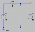
Please Help!! Pretty sure my teacher made an impossible question on my test.

MrAl

Joined Jun 17, 2014
13,761
So will you please tell me what you're getting for the numbers?
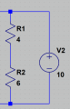
There is only one node that has unknown voltage until you solve for it, and that is the junction between R1 and R2.
Note that the voltage at the top of R1 must be 10v and go from there.
 

Thread Starter

rycooproberts

Joined May 4, 2022
13
V1 = 6
V2 = 4
V3 = 6
Ok so let's say the 10V is sinking current and that's the negative current with a positive 10V. We still have a 16V supply with 12ohms of resistance in series. The 2,4, and 6 ohm resistors get 2.7V, 5.3V, and 8V respectfully. The other voltage source would have to be -11.3 or 11.3 and since it's a sink with no internal resistance, then the only current limit would be the first resistor. It would essentially be a cap of 8amps at 11.3V going into the "10V" source/sink. I'm saying you can't get 10V on that node with these components. You can't say "oh we have 10v across 10ohms here", but then change your perspective for the other components. Am I not understanding your explanation?
 

Thread Starter

rycooproberts

Joined May 4, 2022
13
Then I guess all battery chargers cannot possibly work, right?

Bob
I get your point, but let's look at I3 and it's directional arrow. It is intended to show current flow away from the 10V source. Now if we flip the flow of current and say that it's getting electrical energy (as in a battery being charged), then it effectively creates a bypass around the 4 and 6 ohm resistors. It is only current limited to 8 amps by the 2ohm resistor and then I2 has no juice going across it that can be measured since the path of least resistance would be to the battery. Treating 10V as a sink instead of a source makes calculating I2 impossible, unless I'm just not understanding your perspective.

Edit: Also, that node would have 11.3V going to the battery and not 10V.
 

Alec_t

Joined Sep 17, 2013
15,149
We still have a 16V supply with 12ohms of resistance in series.
It might look like that, but the R2+R3 combo has the 10V supply in parallel with it. That 10V supply has zero resistance.
Edit:
The zero resistance is in series with a pure 10V source.
 
Last edited:

Thread Starter

rycooproberts

Joined May 4, 2022
13
There is only one node that has unknown voltage until you solve for it, and that is the junction between R1 and R2.
Note that the voltage at the top of R1 must be 10v and go from there.
Ok, but the voltage there can't be 10V is my point. Electrical components don't work like "ok there's 10V there so the 6V extra from that other supply get dropped across R1". The Current flows won't work out even if that were true. People keep posting numbers, but they only work in specific sections of the circuit and not across the whole. Please detail the math of the components if you see an answer to the problems.
 

MrChips

Joined Oct 2, 2009
35,017
Ideal voltage source

If you have a 10V ideal voltage source, the voltage across the voltage source is 10V come hell or high water.
The only conundrum is if you place an ideal 0Ω load across the voltage source.

Ohm's Law states that the current I = V /R.

Hence,
I = 10V / 0Ω = ∞A

In other words, the voltage across the 10V ideal voltage source shorted with 0Ω is either 10V or 0V. Take your pick.
 

crutschow

Joined Mar 14, 2008
38,672
but the voltage there can't be 10V is my point. Electrical components don't work like "ok there's 10V there so the 6V extra from that other supply get dropped across R1". The Current flows won't work out even if that were true.
But electrical components do work like that.
What do you mean " The Current flows won't work out"?
They absolutely will.
You seem to have some preconceived, incorrect assumptions that are giving you a problem, including a misconception about how an ideal voltage source works (as these are).

The 10V voltage source has 10V across it under any conditions
It can source or sink an infinite amount of current, but the voltage will always be 10v.
Similarly, the 16V source is always 16V.

So you calculate all the resistor currents based upon those voltages and that will give you all the answers to what the circuit is doing.

Do the calculations and show us the result, instead of just repeating that they don't work.
 

ronsimpson

Joined Oct 7, 2019
4,774
Over thinking. Put a meter across R3 and it will read 6 volts. 6V and 2 ohms = 3A. That simple.
V1, V2 were in a box that you can not see into. You can only see R3. Measure the voltage. Know the current.
1651769728385.png
 

ronsimpson

Joined Oct 7, 2019
4,774
The Gods have declared V2=10 volts. All you can see is R1 & R2. Measure with a meter across R1+R2=10V. Resistance=10 ohms. Current =1A.
1651770017147.png
I can see that the current in V1 & V2 might be confusing. But the current in the resistors is this simple.
 

Thread Starter

rycooproberts

Joined May 4, 2022
13
It might look like that, but the R2+R3 combo has the 10V supply in parallel with it. That 10V supply has zero resistance.
Edit:
The zero resistance is in series with a pure 10V source.
I addressed this earlier. The 16V source either routes current through 12ohms (R1,R2,R3 in series) or the 10V is a bypass and it routes current through just the 2 ohm resistor. so even if the 10V source is a battery being charged or whatever people want to say, the current leaving the 16V supply is either 8amps or 1.3 amps. Neither of which were options on my test.
 

Alec_t

Joined Sep 17, 2013
15,149
The 16V source either routes current through 12ohms (R1,R2,R3 in series)
Yes it does. But it also routes current through the 2Ω resistor and the 10V supply. Ignore the direction of the arrow on the wire going to the 10V supply. Remember, current can be positive or negative. The arrow is not a diode preventing current flow.
 

Thread Starter

rycooproberts

Joined May 4, 2022
13
But electrical components do work like that.
What do you mean " The Current flows won't work out"?
They absolutely will.
You seem to have some preconceived, incorrect assumptions that are giving you a problem, including a misconception about how an ideal voltage source works (as these are).

The 10V voltage source has 10V across it under any conditions
It can source or sink an infinite amount of current, but the voltage will always be 10v.
Similarly, the 16V source is always 16V.

So you calculate all the resistor currents based upon those voltages and that will give you all the answers to what the circuit is doing.

Do the calculations and show us the result, instead of just repeating that they don't work.
Ok, let's say the node about the 4ohm resistor is "J1" and the node below the 6ohm resistor is "J2" KCL for J1 is 3amp going in and 1amp down I2 and 2 amp travelling out which goes into the 10V supply. That supply would have to -10 volts to take current going that way unless it goes in like a battery. However, at "J2" we would need 1 amp coming down from above and 2 amps coming in from the right and 3 amps going back to the 16V supply to satisfy the total current flow in and out of the 16V supply. Am I still missing something?
 

Alec_t

Joined Sep 17, 2013
15,149
KCL for J1 is 3amp going in and 1amp down I2 and 2 amp travelling out which goes into the 10V supply.
Correct.
That supply would have to -10 volts to take current going that way unless it goes in like a battery.
It does behave like a battery; one being charged.
However, at "J2" we would need 1 amp coming down from above and 2 amps coming in from the right and 3 amps going back to the 16V supply to satisfy the total current flow in and out of the 16V supply.
Correct again.
 

crutschow

Joined Mar 14, 2008
38,672
You still see to have the misconception that the voltage supply can't sink current.
You've been told several times that it can.
Why are you not accepting that fact?

You are still waving your arms and not showing us you calculations.
 

BobTPH

Joined Jun 5, 2013
11,609
I addressed this earlier. The 16V source either routes current through 12ohms (R1,R2,R3 in series) or the 10V is a bypass and it routes current through just the 2 ohm resistor. so even if the 10V source is a battery being charged or whatever people want to say, the current leaving the 16V supply is either 8amps or 1.3 amps. Neither of which were options on my test.
R1 R2 and R3 are NOT in series.

R3 is in series with ( (R1 in series with R2) in parallel with 10V).

When you say elements are in series, you are asserting that the current through them is always the same. That is not the case here.


Bob
 

crutschow

Joined Mar 14, 2008
38,672
When you say elements are in series, you are asserting that the current through each of them is always the same.
Or specifically that the current through each element is identical to the others

To be in series, each element must have only one common connection to the other.
If there are more than two elements at a connection, then they are not in series.
 

MrSalts

Joined Apr 2, 2020
2,767
What if the question would have been stated as, a 16v source on the left side is charging the 10v battery on the right side. Show the current flows at I1, I2 and I3.

summary, an ideal voltage source is simply holding a voltage at a constant value - whether the current is coming or going, it's going to hold its 10v level.
 
Top