please help me troubleshooting my project

Thread Starter

nasz

Joined Jan 9, 2010
15
im copy this circuit from some source and just follow the circuit shown. ;( i can't remember where im take it..

what is the trigger frequency and how to get it?
 

Thread Starter

nasz

Joined Jan 9, 2010
15
today i have construct and test the circuit based on the info that i got from this forum...thank you so much!..

the PPM output seems not any problem at all but the output of PWM have a bit confusing..

should be the higher amplitude will get the widest pulse and the minimum amplitude produces narrowest pulse, but i got it inverted...how to change it?

Mr. SgtWookie, is it better to get the smaller trigger frequency for the circuit?..

thank you..
 

Attachments

JoeJester

Joined Apr 26, 2005
4,390
nasz,

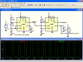
Go to your simulator program and use a square wave for the trigger input and a sine wave for the control input.

Use the 2nd 555 of your circuit only for this experiment.

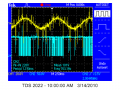
let the trigger frequency equal the 1/2 the control frequency.
let the trigger frequency equal the control frequency
let the trigger frequency equal twice the control frequency
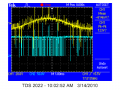
let the trigger frequency equal ten times the control frequency.

You will know from this inspection the answer to your question.
 

SgtWookie

Joined Jul 17, 2007
22,230
Check to make certain that you do not have an "invert" function selected on either channel of your O-scope.

If that was in simulation, turn the pot upside-down and mirror it.

If you had a low-pass filter on the output of the sine wave, it would look pretty good.
 

SgtWookie

Joined Jul 17, 2007
22,230
SgtWookie, is it better to get the smaller trigger frequency for the circuit?..
If you are trying to operate a circuit at high speed and things are not going well, then it is a good idea to slow the circuit down (when possible) and see if things improve. This is not always possible. However, if it can be done, it will help to diagnose a lot of potential problem areas, such as parasitic inductance and capacitance.

The higher in frequency that you go, the greater the effect that parasitics have on a circuit.
 

Thread Starter

nasz

Joined Jan 9, 2010
15
thank you for you info and guideline..im really appreciate it.

i've some question...as i know, for PPM and PWM output, they are varied on the position and width of pulse but not the amplitude..however, from the simulation software, development hardware part and refer to LM555 data sheet, the amplitude of pulse are increase...how this can happen?..

besides, what is the factor or component that can affect the output waveform?..is it potentiometer or frequency from the function generator?


thank you so muchh...
 

retched

Joined Dec 5, 2009
5,207
Both. The frequency of the trigger pulses, and the POT setting on the 555 will cause changes in the outputted PWM signal.
 

Thread Starter

nasz

Joined Jan 9, 2010
15
thank you for you info and guideline..im really appreciate it.

i've some question...as i know, for PPM and PWM output, they are varied on the position and width of pulse but not the amplitude..however, from the simulation software, development hardware part and refer to LM555 data sheet, the amplitude of pulse are increase...how this can happen?..

besides, what is the factor or component that can affect the output waveform?..is it potentiometer or frequency from the function generator?


thank you so muchh...
 

Thread Starter

nasz

Joined Jan 9, 2010
15
owh, ok..

but how can be the output of PPM and PWM amplified?...is there any formula or equation for PPM and PWM?

thank you so much
 

Audioguru

Joined Dec 20, 2007
11,248
for PPM and PWM output, they are varied on the position and width of pulse but not the amplitude.
Correct.

from the simulation software, development hardware part and refer to LM555 data sheet, the amplitude of pulse are increase...how this can happen?
The amplitude of the pulses does not change.

how can be the output of PPM and PWM amplified?
The voltage amplitude of the pulses can be increased with an amplifier or with a digital level-change converter circuit.
 

Thread Starter

nasz

Joined Jan 9, 2010
15
im using LM555 for this both circuit, PPM and PWM... is it LM555 will amplify the their output?..

just for my confirmation, when the value of potentiometer increase the width of pulse will also increase...is it right?..

thank you... ;)
 

Audioguru

Joined Dec 20, 2007
11,248
im using LM555 for this both circuit, PPM and PWM... is it LM555 will amplify the their output?
The output voltage is shown on the datasheet of an LM555. It is about 13.5V p-p when its supply is 15V and the load current is zero. It drops when loaded.

just for my confirmation, when the value of potentiometer increase the width of pulse will also increase...is it right
Correct.
The datasheet of an LM555 clearly shows the width of the pulses changing when the voltage at pin 5 is changed.
 

Thread Starter

nasz

Joined Jan 9, 2010
15
thanks a lot for your explanation...its really help me.. ;)

today, i have testing the circuit again.. i just want to check the pulse that trigger from output from LM555 A1..

i have found that when im increasing the frequency from function generator, the width of pulse from A1 also increase..

but, when im doing the simulation, the width of pulse remain constant even im increase the frequency..

can anybody let me know which one is the right concept?..
the hardware output or simulation output?..

thank you very muchh... :)
 

Audioguru

Joined Dec 20, 2007
11,248
i have found that when im increasing the frequency from function generator, the width of pulse from A1 also increase..

but, when im doing the simulation, the width of pulse remain constant even im increase the frequency..

can anybody let me know which one is the right concept?..
the hardware output or simulation output?
The width of the monostable pulse stays the same when the input frequency is raised. But the pulse appears to be wider because the total time period becomes less.
 
Top