please help me troubleshooting my project

Thread Starter

nasz

Joined Jan 9, 2010
15
hello everyone...im new in this forum and really need your helps..sorry if my English does not very well...

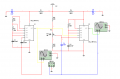
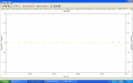
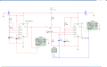
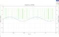
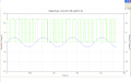
i have problem with my circuit..im successfully get the desired output waveform by using the Multisim but unfortunately, when i construct in on the breadboard, there are no any output waveform..owh, im doing PPM and PWM laboratory kits using LM555..can u guys help me figure out whats' the problem are?..how to troubleshooting the circuit exactly?..


im really need the help!!..thanks for your attention and helps...
 

Attachments

SgtWookie

Joined Jul 17, 2007
22,230
What were you expecting to see?

Try using options that start all nodes in the simulation at 0v.

Then transfer that knowledge to to the breadboard circuit. If something is not essentially in agreement with the simulation, ask yourself what the problem is.
 

Thread Starter

nasz

Joined Jan 9, 2010
15
thanks for you respond..

im expecting to get the PPM and PWM waveform through the oscilloscope..i've checking that were voltage going through the IC on the breadboard..
im sorry bothering you but im not really understand what do you mean by using options that start all nodes in the simulation at 0V?..what option it is?..

thank you so muchh...
 

Thread Starter

nasz

Joined Jan 9, 2010
15
yess, im really getting the desired output in the simulation..

what do you think the problem that will occur during construct the circuit on the breadboard?..

thank you for your attention.
 

Thread Starter

nasz

Joined Jan 9, 2010
15
yes, im intend that the reset to not be tied to Vcc..

In Multisim simulation, i have try to connect reset to the Vcc but the output waveform does not smoothly and not as good as the waveform that i disconnect the reset from Vcc..

thanks for your attention..
 

Thread Starter

nasz

Joined Jan 9, 2010
15
the output from the A1 555 will going to trigger the A2 555, right?. im sorry but how i can get the desired output from simulation but not when im constructing it on the breadboard?.

yes, im intending to do a project about pulse width modulation and pulse position modulation..

thank you for you concern..
 

JoeJester

Joined Apr 26, 2005
4,390
Post a picture of your output ... screen shot saved as .png will work for the simulation output, including the output from A1.

Do you have access to an oscilloscope?
 

Thread Starter

nasz

Joined Jan 9, 2010
15
i've post the picture for the output from the full simulation (output from A2) ..there are a pulse but very small..

i'm also post the circuit on how im getting the output fromA1..hope u can check it for me..tq...the output from A1 is only the straight line..

what do you mean by access to an oscilloscope?..is it for hardware development or what?..

thank you very much..
 

Attachments

JoeJester

Joined Apr 26, 2005
4,390
The oscilloscope would be used to troubleshoot the circuit in the hardware development phase.

You really need to connect the reset to pin 8 on the A1 timer, as well as the resistor. It is not providing any "trigger" signals.

Have you seen the LM555 datasheet section on PWM?
 

Audioguru

Joined Dec 20, 2007
11,248
I think that Multisim is stupid and does not know that a 555 does not work when R2 and its RESET pin are not connected to the positive supply.
 

SgtWookie

Joined Jul 17, 2007
22,230
The RESET pin on the left timer must be connected to Vcc.
I see no purpose for R1 and R6 except to cause problems. Replace them with wire.
I can't be certain because the schematic is so small, but it looks like you are using 10MEG resistors. You should reduce the timing resistors by an order of magnitude (divide the values by 10) and compensate by multiplying your timing capacitor values by 10.

I cannot read the values of the resistors in your CONTROL divider. If the 555 timers are the BJT (transistorized) version, the internal divider is three 5k Ohm resistors in series, for a total resistance of 15k. I think that I see 3MEG for your divider values. Your divider will not be effective, because your resistor values are far too large.
 

Thread Starter

nasz

Joined Jan 9, 2010
15
yess, I have access to use the oscilloscope in the lab..
im posting the circuit that connect the reset pin 8 on the A1 as well as the resistor..There are output pulse from A1… however, the out of PWM were change... It doesn’t look like the early simulation..besides, the waveform output came out limited, it is stop in suddenly..
bad for me, im using the Multisim because that is only software that Im familiar with.. ;(
im also remove the R1 and R6 and replace it with wire…im not using 10Meg ohm resistor..Hope this circuit that im posting is clear for you to check it…
thank you for suggestion and respond..
 

Attachments

JoeJester

Joined Apr 26, 2005
4,390
If you want to get the picture more like the original, make R2 10k and R3 1k. That will reverse the duty cycle of the trigger signal.
 

Thread Starter

nasz

Joined Jan 9, 2010
15
thank you for the suggestion..

when i change the value of R2 and R3, the pulse of output A1 become smaller but that is not a problem..

the output from A2 become better...do you know how to get the exact output PWM just as the earlier output waveform PWM that i showed in my 1st post thread?.

thank you..
 

Attachments

Top