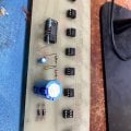
Please help me reverse engineer this LM3914 PCB.

AnalogKid

Joined Aug 1, 2013
12,284
In the meantime, any thoughts on the use of either the MOC3010 or 3030? It seemed to me that that the only significant difference was that the 30s are a zero-crossing model, which I assume isn't necessary when switching a triac. True or not?
Not.

TRIACs automatically turn off at zero-crossings (note that I didn't say voltage or current). They can be turned on at any point in the cycle. It is more gentle on downstream equipment to go for the zero-crossing turn-on model, especially since inrush current is reason for the design.

ak
 

Thread Starter

Failer

Joined Jul 11, 2009
38
I am in agreement with you and that is why I am asking. I can post the two that I was looking at and if I knew how to interpret that data, I wouldn’t be here asking questions that to you must seem very basic. My knowledge is minimal, and the two datasheets for those that I found are in different formats and I can’t pick out the relevant information. That’s why I’m asking here. If you are so inclined, I would appreciate assistance on deciphering their relevant information.
 

Thread Starter

Failer

Joined Jul 11, 2009
38
These optos will be switching Q4025P triacs, because that's what the original design was and thus I have several laying around. They will just be switched by the incoming 120V through the OC, using the gate resistor value that you indicated previously.

Once again, to all.. I appreciate the assistance. My previous experience with things like Heathkit and that sort of thing, while still learning, is really more like model building. I can follow all the steps and put something together, that's not really what I would consider difficult. But I never really considered how I would proceed with something if it wasn't already engineered for me, and I'm realizing now how much of the fundamentals that I don't really know.
 

Attachments

Thread Starter

Failer

Joined Jul 11, 2009
38
Waiting on the resistors* I had to order for the outputs, I guess this is going to be on hold for a little while. I stood the timing and reference resistors up for easier testing in case they needed to be changed. Once everything is good, I'll mount them correctly.
Does anyone see any issues so far?
* I was going to order 1/2 watt carbons for the gate & pulldown resistors. Is this OK, or should I get all fancy with flameproofs?
IMG_7489.jpg
 
Last edited:

Thread Starter

Failer

Joined Jul 11, 2009
38
Success! Sorta. Stage 1 come on immediately, then a pause, then 2, but then no more.
The only center-tap transformer that I could find laying around was a 12V, which gives me 9VDC, which is I assume why I can't get a full sequence yet. I have a regulated 15V supply that I was going to try hooking in behind the diodes, but what transformer voltage should I be looking for with the circuit as designed?
I guess this will be back on hold until I can get the proper input voltage.

Also, with two or three LEDs active, the IC was distinctly warm to the touch, so I didn't want to leave it powered for too long. I know its mostly protected, but I dont think I should be able to feel anything there. Any concerns here? Tell me what I need to be checking.IMG_7509.jpg
 
Last edited:

Thread Starter

Failer

Joined Jul 11, 2009
38
With 3 lit( it took a little while) I get 6.1 at that pin. By now, the VDC has sagged from 9.5 to around 8.
Just for testing, I tried to cheat it by increasing the 120V higher since its on a variac at the moment, but I couldn't raise the 12V substantially more.
 
Last edited:

Thread Starter

Failer

Joined Jul 11, 2009
38
While I'm figuring that part out, I thought I'd turn my attention to the output side. I've been having problems trying to convert from PCB to schematic/wiring in my head, so I wanted to verify, is the following the correct wiring for the output triacs?We just want the 120V present there to gate it on, right?
EG_202213.jpg
 
Last edited:

ericgibbs

Joined Jan 29, 2010
21,602
With 3 lit( it took a little while) I get 6.1 at that pin.
Hi F,
That 6.1V Adj voltage is far too high.
Confirm the values of these two resistors in this image.
E

Added: also a photo shot of the copper track side of the PCB, so that we can check the tracking.

EG 2257.jpg
 
Last edited:

Thread Starter

Failer

Joined Jul 11, 2009
38
Got it, good call! I can barely even see those 5-bands, and even under strong light they're basically impossible to read. I had a 33K in there instead of a 3.3K. And I even put my meter on each one prior to installing them, guess my brain was somewhere else right then. Without any suitable trimmers laying around, a bit of experimentation with the timing leads me to where I wanted with this. That's 10uF plus 2.2.
IMG_7512.jpg

So, the only drawback here is that it takes more than 10 seconds to discharge the timing cap, so while that doesn't seem like a problem for normal operation, I can foresee this being a problem in a quick brownout or power interruption. Is there a way around this, or is it just a byproduct of this method? Once again, I get that this is not really how one would normally build a sequencer of this type.

I thought of wiring a low-value resistor across that cap that would be switched in, off the other poles of the power switch, but that seems kinda kludgey, and doesn't do anything about an interruption. Any thoughts?
 

sghioto

Joined Dec 31, 2017
8,756
A small spdt relay with the normally closed contacts across the timing cap will keep the cap fully discharged when the power is OFF.
 

Thread Starter

Failer

Joined Jul 11, 2009
38
Why are you being coy about that?
TRIACs turn off when the current through them goes to very near zero.
I was somewhat confused by that partial information, but since no other comments were made, I kinda had to let it go. I don't know enough to argue, and if all the people smarter than me here are telling me something, I'll go with what they tell me. You might notice that in the course of this thread, I have asked a great many questions, and not all of them get answered.


A small spdt relay with the normally closed contacts across the timing cap will keep the cap fully discharged when the power is OFF.
I have a tiny little reed relay that would be perfect for this but is that the best option here? That's along the same lines as I was thinking, but it seems kinda... idk. I know it'll work but does anyone have any other ideas?
 

ericgibbs

Joined Jan 29, 2010
21,602
the only drawback here is that it takes more than 10 seconds to discharge the timing cap
hi F,
Regards the discharge time.
What other types of IC's do you have on the bench, analog and digital?
E
 

Thread Starter

Failer

Joined Jul 11, 2009
38
hi F,
Regards the discharge time.
What other types of IC's do you have on the bench, analog and digital?
E
I'm not following.
Like, available? Bunch of 555s. Loads of antiquated op-amps and 70s-80s era transistors. An EGC101, if someone wants to play with that.
 

eetech00

Joined Jun 8, 2013
4,735
In the meantime, any thoughts on the use of either the MOC3010 or 3030? It seemed to me that that the only significant difference was that the 30s are a zero-crossing model, which I assume isn't necessary when switching a triac. True or not?

Earlier, I said that I suspected that the original unit used the 3010s, and the reason that I had guessed that was that I found two packages, each containing 10 OCs. The 3030 package was still unopened, and the 3010s had 6 missing, I assumed for this project, but that's simply conjecture on my part. Is there any other important differences, and if so, which would be most appropriate for this application?
Suggestions:
1. Since you do not know the type of AC load (resistive or inductive), use Zero crossing optos.
2. The 3030 has a recommended input trigger current of 30mA. That is the MAX current limit for the LM3914. To avoid this, use the 3031, as it has a recommended trigger current of 15mA.
3. The LM3914 programming resistors need to be adjusted to supply the required opto trigger currents. For the 3031, use R1=820, R2=470 (Sets IF=15mA, Vref=2v).
4. Change 100uf to 470u to further reduce supply ripple voltage.

Note that the design doesn't provide a linear step time interval (each step is not 1 sec apart).

See below.
I used a bar graph LED model to represent the 10 OPTO LEDs, each LED represents an OPTO LED.

1791316281386.png

1791316337281.png
 

Thread Starter

Failer

Joined Jul 11, 2009
38
Thanks, I appreciate the input & analysis. I will take your point one at a time and see if that helps any. Also, is that simulation a file that you can/would share with me? I downloaded that program before, but haven't really figured how to use it. Would the simulation allow me to play with the values?

1. Since you do not know the type of AC load (resistive or inductive), use Zero crossing optos.
I figured that. In the past, I may or may not have tried switching stereo equipment with regular relays - yeah, not a good idea.
Still, though...I thought that using a triac was going to be zero-crossing as a matter of course, thus that the optocoupler action wasn't relevant. I have since been told otherwise, but don't really understand the explanation given thus far.

2. The 3030 has a recommended input trigger current of 30mA. That is the MAX current limit for the LM3914. To avoid this, use the 3031, as it has a recommended trigger current of 15mA.
Hmm, that sounds reasonable. But I'm not going to buy any more optos. I already have these, and either the 3010s, or the 3030s were what this was designed for, although I don't know which. I currently gave the 3030s socketed in. With the stage active, the indicator LEDs are fairly bright. Is there a way to directly measure the current through that LED & the optocoupler? DMM in series?

3. The LM3914 programming resistors need to be adjusted to supply the required opto trigger currents. For the 3031, use R1=820, R2=470 (Sets IF=15mA, Vref=2v).
Can you elaborate on this for me? I see the section about current programming in the datasheet, can you kinda reframe that in...uh...layman's terms for me? Wouldn't changing that change the timing as well?

4. Change 100uf to 470u to further reduce supply ripple voltage.
That cap is actually a 1000uF. Once again, I already had it. Plus, I suspect that it was the original value anyway. The reason I have them, is because my father used those same caps for almost any linear power supply that he built. The fact that it fit perfectly in the pads is another clue.

Note that the design doesn't provide a linear step time interval (each step is not 1 sec apart).
That was brought up previously, and I confirmed that during testing. For my application, I think that is a feature, not a bug. With the earlier stages switching input devices, crossover, pre-amp, EQs, etc. and the later switching large power amps, I think the slight staging rate ▲T works just fine.
 
Last edited:
Top