Facebook
 Google
 GitHub
 Linkedin
i was thinking about the filter caps or the two resistors regulating the output (but those i just check them)
so now the fun part starts. try to find that darn component!Other components shorted could make the output of the regulator appear lower, due to it being overloaded and unable to maintain regulation. If this is happening, the regulator will get physically hot rather quickly.
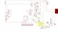
 . But to me it look like one or both components pin in the red circle are not soldered properly