Placing Rectifier Diode in Neutral Wire of House Wiring

MaxHeadRoom

Joined Jul 18, 2013
30,871
Certainly I could be wrong as so far I have never attempted to construct a current transformer, but my impression is that only 20 turns of #24 wire would produce very little voltage. An "AC Line Current Detector" that I found on the web by Bill (?) Bowden calls for 800 turns or more of #30- #40 wire wound on a1 inch diameter U- bolt.

He writes, "The magnetic pick-up [his coil on a U-bolt] produces about 4 milli-Volts peak for a AC line current of 250 mA."

Regards,
Pete
The operative word here is current, it is designed to produce an alternating current in its secondary winding which is proportional to the current being measured in its primary.
See the link I mentioned in post #35 for a complete description.
 

crutschow

Joined Mar 14, 2008
38,912
He writes, "The magnetic pick-up [his coil on a U-bolt] produces about 4 milli-Volts peak for a AC line current of 250 mA."
As noted, that does not tell us much.
A current transformer generates a current (surprise) so any voltage it generates is based upon the load the current is flowing through.
Need to know the load when he measured the 4mVpk.
Was it just the impedance of the measuring instrument (presumably a scope)?
 

MisterBill2

Joined Jan 23, 2018
28,492
I don't think that we ever learned just what the purpose or intent was for this project. Many years ago "Popular Electronics" magazine published an article that used a similar diode arrangement with some transistor amplification to switch on a stereo system main amplifier whenever any of the devices producing an input were switched on. Why that just popped into my head I am not sure. So the concept is valid but the application here is wrong.
 

Reloadron

Joined Jan 15, 2015
7,975
If all you care about is Yes/No current as in the heating element is either On or Off rather than try and build a current transformer solution there are devices like these and similar devices. They illuminate at currents as low as 0.75 Amp and for lower currents you can simply loop a conductor multiple times through the hole. Simple and easy requiring no electrical skills and also non intrusive. The link has them at $13 USD but I have gotten them for about $10 USD. The link is for CR Magnetics and here are the specific data sheets. I use them for my sump pumps and have used them to let me know when heating elements fail open. Plain and simple. My take is a heating element is On drawing current or Off drawing no current? That what you are after?

Ron
 

MisterBill2

Joined Jan 23, 2018
28,492
OK, devices that act like CTs but are a sealed module. I have a device similar to that but it runs a whole lot more than $13. It is powered by 24 VAC and it includes adjustable limits and a relay contact output. .But it is a building system grad product, and so it would cost more. And now that it is clear that it is for monitoring heater tapes and not measuring current, and that it needs to trigger on about one amp, or possibly 3 amps, it is clear that a current transformer for each heater is the best choice. And quite probably a home-made CT powering either an LED, or a small pilot lamp bulb, would work quite well. Such a CT could possibly even be located inside the outlet box where the heater cable is plugged in.
AND an important suggestion is to NOT have that circuit GFCI protected. I have seen that, where a GFCI tripped because of water getting onto the plug, with the result that the faucet froze and burst from the ice. Really Dumb!!
 

Reloadron

Joined Jan 15, 2015
7,975
OK, devices that act like CTs but are a sealed module. I have a device similar to that but it runs a whole lot more than $13. It is powered by 24 VAC and it includes adjustable limits and a relay contact output. .But it is a building system grad product, and so it would cost more. And now that it is clear that it is for monitoring heater tapes and not measuring current, and that it needs to trigger on about one amp, or possibly 3 amps, it is clear that a current transformer for each heater is the best choice. And quite probably a home-made CT powering either an LED, or a small pilot lamp bulb, would work quite well. Such a CT could possibly even be located inside the outlet box where the heater cable is plugged in.
AND an important suggestion is to NOT have that circuit GFCI protected. I have seen that, where a GFCI tripped because of water getting onto the plug, with the result that the faucet froze and burst from the ice. Really Dumb!!
Yes, you can get models that have set limits but if you just want to know if a heater element is drawing current as in On or Off the little molded CT with a diode and LED works fine. You can also do the classic wire turns around a magnetic reed switch. I liked using the ones I linked to because it made it easy at a glance to monitor 72 heating elements. Open elements are easy to see. :)

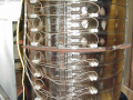
Each half element id 3 KW 240 Volts. Each complete element is 6 KW 480 volts. Top to bottom there are 72 elements divided over 3 phases, 24 per phase. All in all 432 KW when coming up to temperature.

Clave3.png

Checking the tension and yes, I was much younger. :)

Me Clave.png

Over time as elements fail things take longer and longer to get hot. Rather than shut down and have a tech check element by element at a glance I know exactly where failures are and how many failures we have. Generally we waited for about 10 because what you see pictured is covered with large insulated covers, top to bottom. The vessel ID is 24" and OD is 30" of 316 stainless steel.

Ron
 

Thread Starter

PeteHL

Joined Dec 17, 2014
596
Need to know the load when he measured the 4mVpk.
Was it just the impedance of the measuring instrument (presumably a scope)?
He doesn't explicitly state what the load is when he measured 4 mVpk. However in the circuit diagram of his device, he does show his coil at input to a 470 Ohm input resistor in a circuit with an op amp configured as an inverting amplifier. The resistance of the feedback resistor of the inverting amp is 100k.

-Pete
 

MisterBill2

Joined Jan 23, 2018
28,492
OK, it seems that if a hand-made CT is made that some experimenting will be required. Fortunately that is rather easy to do, if some incandescent light bulbs are available to use as loads, and iif the wattage rating of tyhe heaters is known. If enameled wire is used then quite a few truns can be wound on it, which will deliver a higher voltage per amp. And if there is room, a second turn of the one mains winding through the core can be added, doubling the output.
I have disassembled a failed GFCI device and I see that the coil that it has is a very large number of turns of very fine wire. But given that a US GFCI i intended to trigger with just a very small current, that is a different picture completely.
 

BillB3857

Joined Feb 28, 2009
2,573
Years ago, I needed to see how many times a sump pump ran. I disassembled an old GFI outlet and salvaged the current transformer from it. Like many have said, only one wire of the source goes through the center of the transformer. A series resistor, a diode and LED pointed at a photo diode (mounted inside a soda straw) gave me an interface to a Radio Shack digital counter. Worked great!
 

Thread Starter

PeteHL

Joined Dec 17, 2014
596
Bowden shows a circuit where the current transformer (sensor) activates a mechanical relay. Perhaps that would account at least in part for the relatively high number of turns of his transformer.

I'm not clear about the difference between voltage and current transformers. It seems to me that the only difference is that the current transformer is producing a current from the much weaker magnetic field of a single or a few turns of wire than is the case with the voltage transformer with a primary that produces a relatively much stronger field by input voltage applied to a coil of many turns.

Looking at the tutorial that MaxHeadRoom provided a link to in another thread, apparently current in the secondary of a current transformer decreases with increasing turns of the secondary. That is very surprising to me. A good tutorial-

https://www.electronics-tutorials.ws/transformer/current-transformer.html

Regards,
Pete
 
Last edited:

Thread Starter

PeteHL

Joined Dec 17, 2014
596
If all you care about is Yes/No current as in the heating element is either On or Off rather than try and build a current transformer solution there are devices like these and similar devices. They illuminate at currents as low as 0.75 Amp and for lower currents you can simply loop a conductor multiple times through the hole. Simple and easy requiring no electrical skills and also non intrusive. The link has them at $13 USD but I have gotten them for about $10 USD. The link is for CR Magnetics and here are the specific data sheets. I use them for my sump pumps and have used them to let me know when heating elements fail open. Plain and simple. My take is a heating element is On drawing current or Off drawing no current? That what you are after?

Ron
Those current sensors are fairly inexpensive (not really inexpensive), however, the indicator LED only 11 inches away from the current transformer hardly makes it a remote indicator. In my case, the LED would need to be about 20 feet distant from the transformer. Is there any reason why a longer lead to the LED couldn't be used?

My suggestion to the company would be to provide connectors on the current transformer and the LED so that the customer could easily attach the length of lead needed according to how remote the LED must be.

Regards,
Pete
 

Reloadron

Joined Jan 15, 2015
7,975
Those current sensors are fairly inexpensive (not really inexpensive), however, the indicator LED only 11 inches away from the current transformer hardly makes it a remote indicator. In my case, the LED would need to be about 20 feet distant from the transformer. Is there any reason why a longer lead to the LED couldn't be used?

My suggestion to the company would be to provide connectors on the current transformer and the LED so that the customer could easily attach the length of lead needed according to how remote the LED must be.

Regards,
Pete
I have extended the leads on them to about 20 feet. I use a few on my sump pumps.

Ron
 
Top