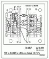
PIR Sensor to BC547 to LEDs

Thread Starter

allenpitts

Joined Feb 26, 2011
163
Hello AAC forum,

Have a couple of projects complete, couple in flight, and several
planned using a PIR sensor (hc-sr501) to control LEDs. The applications
are in closets, stairways and cabinets.

Simple_PIR_Circuit_200203.gif
Have used this Simple PIR Circuit as a sort PIR component
tester but am thinking about a tester that also includes
a transistor.
PIR_to_BC547_200408_280_x_200.gif

The simple circuit is one found on line. The PIR to BC547
to LEDs
is an extension of that based on one found at
PIR_to_Transistor_to op_amp

The question is: Is the R4 resistors necessary?
It seems like R3 is limited the flow of current from the positive rail.
But not sure it would protect the LEDs.
Thanks.
Allen in Dallas
 

Attachments

Audioguru again

Joined Oct 21, 2019
6,688
The PIR is connected to the transistor, but the transistor is not connected to the LEDs. The LEDs are connected to the battery with the R4 current-limiting resistors and they light all the time.
If the LEDs are 5mm ordinary red 1.8V ones then they are burned out with a current that is (9V - 1.8V)/220 ohms= 32.7mA each. They are usually 20mA each.
 

Thread Starter

allenpitts

Joined Feb 26, 2011
163
Hello SamR, AudioGuru, and electricSpidey,

Is my face red.
Was trying to use the transistor as a connection between voltage and ground instead of a switch on the ground rail. Breadboarded the schematic and it stayed on all the time because the Q1 was not deployed as an on/off.
View attachment 203933
This one works.
Also the 100k ohm resistor is not only not needed but
if included prevents the LEDs from lighting.
Assuming that PIR output is driven high not just with a pull up R a modified print is shown.View attachment 203937
Hello Bernard,

Thanks for the redraw. So the 10k between the PIR and ground is not necessary and should increase value of the other two resistors. PIR_to_BC_547_to_LEDs_200410_413_x_500.gif
This is the schematic applied to a prototype board. Since it is planned to do a bunch
of these w 555 timers for closets and stairs reducing the number of
components will reduce the size of the PCBs.
Allen in Dallas
 

ElectricSpidey

Joined Dec 2, 2017
2,774
I'm curious, do you test your circuits on breadboard before planning these final boards?

I only ask because people seem to have a problem driving loads from PIR modules, instead of logic inputs.
 

Audioguru again

Joined Oct 21, 2019
6,688
I'm curious, do you test your circuits on breadboard before planning these final boards?

I only ask because people seem to have a problem driving loads from PIR modules, instead of logic inputs.
The PIR used here is an old one designed to drive old fashioned TTL logic that needs a low input current when it is logic high (and the high is only 3.3V) but needs a high input current when it is logic low.
 

Thread Starter

allenpitts

Joined Feb 26, 2011
163
Hello AAC Forum, Audioguru and ElectricSpidey,
The method used is to do a schematic, then bread board from the schematic and then a prototype PCB from the breadboard.PIR_to_Transistor_to_LED_breadbrd_photo_200412.JPG

PIR_to_Transistor_to_LED_proto_photo_200412.JPG

This circuit, PIR to transistor, is sort of the front end of a project which uses a to transistor, instead of turning on three LEDs, triggers a 555 timer:
PIR Sensor (Motion detector) to 555 timer to LED array
Because there are dozens of these lights planned, the prototype with the timer is moved to a custom, multi-layer PCB.
The bread board takes 20 square inches. The prototype takes 8 sq inches. The custom PCB takes 1.5 sq. inches.

The schematic to breadboard is the easiest because the application of the circuit logic to a breadboard w/o soldering is faster and easier to troubleshoot and fix. The toughest transition is from breadboard to prototype PCB. There are lots of jumper wires and the logic gets lost. And if a non sequitur is encountered desoldering and resoldering is involved in the refactor.

When the prototype board works, like the one marked PIR Sensor to 555Monstable to LEDs displayed in the forum thread linked to above, then a custom PCB is designed using a software called DipTrace. Have used Eagle CAD and several others but as timing consuming as Dip Trace is, it is still more intuitive and easier to use than any of the half dozen PCB layout programs trialed.

The PIR used here is an old one designed to drive old fashioned TTL logic that needs a low input current when it is logic high (and the high is only 3.3V) but needs a high input current when it is logic low.
Not hundred percent sure what this means. I do know I have used the larger PIR, HC-SR505 which has adjustments for distance sensitivity and the length of time the PIR sends a signal. The little brother HC-SR501 is smaller and has no adjustments. Both, when their comparator is tripped, send out a +3V signal.

A PIR was used to trigger an MP3 player and 30 watt amplifier. Scares the crap out of trick or treaters in October.,
I posted it at Completed Projects Index but it looks like it got erased. PIR to MP3 player is a link to that project at Instructables.

Thanks.

Allen in Dallas
 

ElectricSpidey

Joined Dec 2, 2017
2,774
I noticed in post #6 you still have R1 in the circuit, are you sure you want to keep that?

The reason I ask is because it may function with one PIR but not every PIR, so if building a "test" board, you may want to ditch R1 and just test at the voltage range of the PIR in test.
 

Audioguru again

Joined Oct 21, 2019
6,688
The HC-SR505 PIR datasheet also says its output voltage and output current are fairly low.
Then does the little transistor have enough base current for it to turn on the 3 LEDs?
 

Bernard

Joined Aug 7, 2008
5,784
Seems that the PIR output comes from a 3.3V source thru a 1k to the output, limiting the base current to about 2.7 mA. or about 10 mA / LED.
 

Thread Starter

allenpitts

Joined Feb 26, 2011
163
Hello AAC forum, Electric Spidey, AudioGuru and Bernard,

Electric Spidey:
In post #10
in post #6 you still have R1 in the circuit, are you sure you want to keep that?
Looks like R1 is a 10k ohms resistor between the PIR ground and the ground rail. Have tried it with and without.
I agree, R1 is superfluous. It works both ways. The only difference I see is the LEDs sort of fade out with R1 in. Without R1 the LEDs go off immediately when the PIR stops sending the three volts

AudioGuru:
The HC-SR505 PIR datasheet also says its output voltage and output current are fairly low.
Then does the little transistor have enough base current for it to turn on the 3 LEDs?
The transistor, BC547, closes the circuit to ground and turns on three LEDs fairly brightly.
In the post marked, PIR Sensor (Motion to 555etector) to 555 timer to LED array linked herewith,
there is a schematic titled PIR Sensor to 555 Timer Monostable w Extension Transistor, dated 200210
which outputs to another BC547 which is the schematic used to build this breadboard:
P5L_PIR_555_LED_breadboard_photo_172_x_600_200412.JPG
The output from the PIR, as mentioned, is about 3 volts. The output from the 555 is
about 7 volts or 2 volts lower than the supply voltage. In this breadboard the BC547 opens
current ten LEDs that burn brightly.
But voltage is only part of the equation. The specs on the BC547 says:
Base Current : 5mA maximum
So it is understood that 5mA is pretty small.
So the if the current is 7 volts from the 555, a resistor
required to keep from burning up the transistor. And this is where the limitations
caused by me being a web developer and not an electrical engineer is realized. So leaving the PIR
alone and focusing on the 555, how does one figure out what value for the resistor labeled
3.3k between the output of the 555 and the base of the BC547 is required?
It is surmised that using V/R=Amps, The 7 volts divided by 3.3k ohms .0021. So I guess this is
2mA which is enough to saturate the BC547 but not enough to burn it up.

Bernard:
Seems that the PIR output comes from a 3.3V source thru a 1k to the output, limiting the base current to about 2.7 mA. or about 10 mA / LED.
Seems Bernard anticipated where I was going in the resistor value question to AudioGuru. Except it seems the 3.3V source
is going thru R2 which is 470k ohms , not 1000 ohms. But maybe I'm looking at the wrong schematic.

The next step is the custom PCB:
P5L_200331_4L_PCB.jpg
Will advise when I get the PCB and get it loaded.

Thanks.

Allen in Dalla
 
Last edited:

Bernard

Joined Aug 7, 2008
5,784
The 1k is internal to PIR package. If in doubt, measure output of HC-SR505 , about 3.3V?; then add a 1k from output to ground & remeasure, about 1.6V? then internal 1k is there.
 
Last edited:

Audioguru again

Joined Oct 21, 2019
6,688
The 3.3k resistor does not have 7V across it because the base is at +0.7V so the resistor has 6.3V across it causing the base current to be only 1.9mA.
The datasheet for the old BC547 shows a maximum allowed current of only 100mA and it works poorly above only 50mA. Why not use a more powerful little 2N4401 or BC337 instead?
 

PAFMC01

Joined Mar 20, 2013
12
Hello AAC forum,

Have a couple of projects complete, couple in flight, and several
planned using a PIR sensor (hc-sr501) to control LEDs. The applications
are in closets, stairways and cabinets.

View attachment 203869
Have used this Simple PIR Circuit as a sort PIR component
tester but am thinking about a tester that also includes
a transistor.
View attachment 203870
Hi Allenpitts,
Others have answered your direct questions, but consider this option: You show 3 LEDS, with individual current limiting, in parallel. If you are only using 3 leds, why not run them in series with a single current limiting resistor adjusted to suit? That way, assuming you want to run them at 20mA per led your total draw for the leds will be ....20mA!. If you run them as separate strings it is 3x20=60mA. If these are to be cupboard lights I recommend you do not run the thing off 9 volts, as 9 volt batteries (the rectangular type) do not have much storage. Better to use one of the many available 12 volt batteries, which gives you more options as to size/capacity.

I have had a similar system running for 4 years now as pantry lighting. I used standard runs of strip leds which have their own inbuilt limiting resistors. Because my total draw was around 1400mA - I like it bright - I ran the strips via a 2N3055 power transistor, because I had a bunch of these to hand. A smaller power transistor would be fine, but probably not cheaper. I also took the diabolical liberty of running the output of the SR501 directly into the base of the 3055 without any external limiting, as a close look at the SR501 circuitry showed it has a limiting resistor of 1K on the output anyway. Absolutely no adverse issues.

Using your (acknowledged as erroneous) diagram as a starting point, R2 becomes zero, the LEDS go all in series with one resistor also in series with them, and the whole string replaces R3

If you decide to save current (and battery life) and run the leds in series this calculation for the LED limiting resistor may help:
R= (Vcc - nVd) /I
Vcc is the battery voltage
I is the desired led current
Vd is the characteristic LED voltage - typically 1.7Volts for a red LED, and around 3 volts for a white LED (but check yours)
n is the number of LEDS in your series string. Purists might like to refine that formula, but it is more than accurate enough for the purposes in hand.

As an exercise you might like to calculate the resistor dissipation, and the current draw at battery end-of-life (around 10.5volts).
From that formula, you can see that the sum of the characteristic LED voltages may not be more than the supply. It is good practice to adjust Vcc or n to leave some "headroom" so the supply still exceeds the LED voltages at minimum battery voltage.

The SR501 is a good device, but there is a smaller one: Looks like this, and the model is SPS50506S

:
PIR.jpgThis model can be mounted to be more discreet. The tiny PIR does not have a time adjustment, but by adding a capacitor in parallel with its existing timing cap you can increase the on- time. The only minor down-side is that increasing the on-time also increases the dead time - the interval after turn-off that the device does not respond to fresh movement.

If you are going to have a number of pantry / cupboard lights around the house you might consider running them from a central low voltage supply. Infeasible in a 2 storey house though, unless the pantries are upstairs.

Enjoy your foray into building stuff...
 
Last edited:
Top