Facebook
 Google
 GitHub
 Linkedin
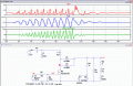
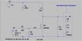
I have reduced the voltage to 5V because, ultimately, i have to make everything working on 5V only, I cannot use a 12V supply as it will be battery operated.hi h.y,
Why have you have reduced the supply voltage from 12v to 5v.?
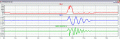
Have you tried reducing the On period of the 1MHz drive.?
E
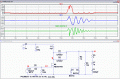
No, I haven't tried reducing the on period yet, but eventually, I will do that.
I am having some trouble in calculation for transformer, as it tuns out there are no 1 Mhz transformers used yet, so I cannot understand, which core to use, wire gauge and no.of turns...can you help me out with it as per your high skills and experience.
Thanks..
")