Piezo sensor/Mic 5V preamp Circuit ideas or sugesstions

Thread Starter

djbondango

Joined Jan 17, 2020
17
Hi all,
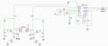
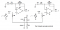
Looking for ideas on Amplifying 2 piezo sensors/Mics with Impedance > 1 MOhm

I am restricted to a 5V regulated supply only.

This was my plan...

Any help greatly appreciated :)
mpc6002+TPAIC.png
 

AlbertHall

Joined Jun 4, 2014
12,345
The non-inverting amplifier input sits at GND potential. Therefore, with no input the inverting input and the output will also sit at GND potential.
Now when the input from the sensor goes positive the output will go positive too. However when the input goes negative the output cannot go negative as it already at GND so the output will be a severely clipped version of the input. The amplifier should be configured more like this:
1579391192461.png
 

Thread Starter

djbondango

Joined Jan 17, 2020
17
Thanks Guys,
Going with Alberts explanation I have changed the circuit to the following..

amended.png


As per the TPA6123A i have just used C1/C6 on its inputs at 1UF

Thanks for all the help so far :)
 

MisterBill2

Joined Jan 23, 2018
18,167
If the signal input were to the inverting input then the bias resistors setting the positive input bias level would not be shunting the input signal. This will allow a greater load impedance to be presented to the piezo devices, and that may provide a benefit. I am guessing that U2 shown in the first post is a stereo amplifier of some kind. IN the first circuit there is only one signal inversion, while if the inverting inputs on the first stage were used then the final output signal would move in the same sense as the input signal. That may or may not matter.
 

Thread Starter

djbondango

Joined Jan 17, 2020
17
Thanks for all the replies, I am kinda new to OPAMPS and Audio design so greatful for all the input so far.
Here is current schematic..Basically shifting Piezo signals to near consumer line level (as can then go to Amplifier/headphone Amp)
 

Attachments

Audioguru again

Joined Oct 21, 2019
6,672
Amplified piezo "sensors" feeding headphones? What sounds are you listening to?

The MCP6002 is too noisy (hiss) for audio. You should use an audio opamp like an OPA2134 dual which has low noise but also has a minimum supply of 5V.

How much amplifier gain do you need? The first preamp had a gain of 101 and the 2nd and 3rd preamps have a gain of only 11.
 

Audioguru again

Joined Oct 21, 2019
6,672
If the signal input were to the inverting input then the bias resistors setting the positive input bias level would not be shunting the input signal. This will allow a greater load impedance to be presented to the piezo devices, and that may provide a benefit.
Absolutely not. The inverting input of an opamp that has negative feedback is a virtual ground with an extremely low input impedance. If the inverting opamp uses a 1M feedback resistor and a 10k input resistor for a gain of 100 then the input impedance is 10k which is much too low for a piezo sensor.
 

Audioguru again

Joined Oct 21, 2019
6,672
I notice that the voltage divider for biasing the opamp feeds half the power supply noise to the opamp + input. Therefore the voltage divider should have a filter capacitor to ground then one more resistor to bias the opamp + input.
 

Thread Starter

djbondango

Joined Jan 17, 2020
17
Amplified piezo "sensors" feeding headphones? What sounds are you listening to?

The MCP6002 is too noisy (hiss) for audio. You should use an audio opamp like an OPA2134 dual which has low noise but also has a minimum supply of 5V.

How much amplifier gain do you need? The first preamp had a gain of 101 and the 2nd and 3rd preamps have a gain of only 11.
As said this is new to me, so glad for any suggestions and help. For now i am not to worried about sound quality as such. The Piezos are automotive sensors that will be listening to noise within automatic transmissions. The audio will be passed through FFT for analysis. I can change to OPA2134 later, but first wanted to get a basic schematic or working principal to get an output to near consumer line level.
 

Audioguru again

Joined Oct 21, 2019
6,672
The automatic transmission in a car does not produce hiss sounds so I guess the MCP6002 dual opamp will be fine.
I notice that the polarity of your C9 (for HPVSS pin8) is backwards. Pin8 is a negative DC voltage that is produced.

Maybe the preamp gain should be adjustable since you do not know how loud are the sound levels. For FFT you do not want the outputs of the preamp to produce clipping.

Hee, hee. Why stereo? Which car has two transmissions?
 

Thread Starter

djbondango

Joined Jan 17, 2020
17
The automatic transmission in a car does not produce hiss sounds so I guess the MCP6002 dual opamp will be fine.
I notice that the polarity of your C9 (for HPVSS pin8) is backwards. Pin8 is a negative DC voltage that is produced.

Maybe the preamp gain should be adjustable since you do not know how loud are the sound levels. For FFT you do not want the outputs of the preamp to produce clipping.

Hee, hee. Why stereo? Which car has two transmissions?
Hi yes, sorry C9 was just reference is for schematic but will be just an 0402 as specified in datasheet.
The stereo aspect is just how each sensor will be assigned its own audio channel - As placement of piezo sensors will be varied.

Still kinda lost now though on what needs changed on the circuit lol
 

Audioguru again

Joined Oct 21, 2019
6,672
You do not have a power supply, instead you have a DC to DC converter that has a lot of 100kHz switching noise.
The original circuit that amplified the power supply noise would be clipping with all this noise. Therefore the 470nF filter capacitor I added to the voltage divider and third and fourth bias resistors are important.
 
Top