Piezo "Hit" Sensor?

Thread Starter

rusirius

Joined Jan 9, 2008
12
Hi all. My electronics experience basically comes from some very rudimentry projects (i.e. learning lab type stuff) and such, so while things like logic circuits give me no problems, I'm afraid things such as this do...

Let me give a brief overview of what I'm trying to do, and hopefully someone can help me out... I'm sure what I'm trying to do is extremely simple, it's just my lack of knowledge that's making it difficult!

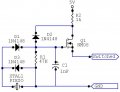
I have a piezo sensor mounted to a pad. Whenever that pad is "struck" or jarred in any way (above a certain threshold), I need to provide a closure across two wires. I don't know how time sensitive the closure is, so I don't know if I need any hysterisis or not.

I've played around trying to get various things to work and just haven't gotten anywhere with it. Is it possible someone could offer up some help?
 

Thread Starter

rusirius

Joined Jan 9, 2008
12
Hrmmm.... Maybe I just came up with something... Can anyone comment on this?

The wires I need to provide closure on already has a +5v current limited source on one...

Is it possible I could do something as simple as .... well, let me try drawing it instead of trying to describe it....

circuit.jpg

Thoughts? Could it be this simple?
 

beenthere

Joined Apr 20, 2004
15,819
That might do for a near-instantaneous operation. I would want to make sure the voltage on the gate did not rise above 20, or the FET will become toast.

If the function is to be retained - like a strike on/strike off control - then the FET could make a current path through a latching relay coil. You might want some filtering on the gate, though.
 

Thread Starter

rusirius

Joined Jan 9, 2008
12
Thanks! I gave this a try tonight and ran into a problem... Again I'm sure it's something really easy to fix, but with my extremely limited knowledge I'm just not sure how to handle it...

The circuit seems to work great... For one or two hits... The problem is, I'm assuming a charge builds up on the piezo itself? I'm wondering if the "ground" isn't really a ground but rather just an "input"?

Basically what's happening is, after a couple hits, the mosfet stops working... When I go to check it out, as soon as I connect a scope probe across the piezo it starts functioning again... As a side note, when the mosfet is working, it's showing quite a bit of hysterisis... Basically a quick "hit" on the piezo will result in a good half second or more of the fet being on... The harder the hit, the longer it stays on... Not exactly the behavior I'm looking for...

I'm guessing I just need a way to shunt the power, which my limited knowledge tells me SHOULD have been happening through the ground, but since it's apparently not a ground it's not working...

Is there a way to get this to work with a slight modification? My only other thought is to put battery power on it instead and drive a relay, but if the circuit WAS working properly I'm not sure it would be enough of a pulse to actually drive the relay?

Again any advice will be MUCH appreciated!
 

beenthere

Joined Apr 20, 2004
15,819
You are storing charge in the capacitor you have on the gate. FET gates look like capacitors already, and the only way for the charge to bleed off is through that 4.7M resistor.

Put the .1 cap at the cathode of the diode. Put 100 ohms in series with the gate (between the diode and the gate lead), and a 47K resistor from the gate to ground. The changes may let it work more like what you want.
 

Thread Starter

rusirius

Joined Jan 9, 2008
12
Question... You said put the .1 at the cathode... That's where it is now is it not? Can you clarify exactly where you want the cap to shift to? I follow the rest and will give it a try as soon as I can! ;)
 

SgtWookie

Joined Jul 17, 2007
22,230
Just to be sure I'm interpreting your circuit diagram correctly, I re-drew it using CircuitMaker Student. Please see attached.

If my interpretation is correct, I think what's happening is that your piezo-generated charge on the gate isn't being drained off quickly enough. I think that if you sat there and waited for a while, the charge would eventually drain off enough to shut off the MOSFET. You simply have far too large of an RC time constant on the gate.

The impedance of the gate itself is extremely high, so really the only path to ground that the charge has to dissipate is the 4.7M resistor. It works for the first couple of hits because the capacitor has not had sufficient time to build up a charge, but eventually the threshold is passed where there is enough stored voltage that the gate takes a long time to reach ground potential, thus seems like it never cuts off.

Scope probes have some capacitance to them, and the input impedance to an o-scope is MUCH lower than the gate of a FET/MOSFET.

Try dropping the resistance to 470K first. If that doesn't help, try dropping it to 47k, then try reducing the size of the cap.
 

Attachments

SgtWookie

Joined Jul 17, 2007
22,230
Here's a newer version.

Note D2 - it's there to prevent the voltage on the gate from becoming too high. It "clamps" it to a maximum of 0.6V above your supply voltage.

Also note that I cut the resistor size to 47K and the cap to 1nF (0.001uF)
 

Attachments

Thread Starter

rusirius

Joined Jan 9, 2008
12
First let me thank both of you for your awesome help! I truely do appreciate it! The reason I love little projects like this is not just for the obvious use of the circuit, but for the learning experience it provides, and these sort of comments and explanations are exactly what I love and need!

Now on to the circuit... In your updated drawing, let me elaborate on a couple of things... Your new drawing has the two power rails (+ and ground) as well as an output... Keep in mind with my project I really ONLY have the two power rails... It just so happens that my rails are ALSO my output... When the +5v is pulled to ground, it registers a "hit"... So essentially the entire point of this project is to pull the +5v to ground when the piezo is struck...

I'm not sure in your drawing if you just seperated it to make more sense, or if you actually thought I had seperate rails and output...

Now... Here's an important (or at least I THINK it's important) bit of information... Last night when I was working with this, I was kinda thinking along the exact same lines... That the cap was charging and not discharging enough... However, up reducing the resistance by half (another 4.7M in parallel) I didn't seem to notice any difference at all... Looking at your specs of 47k, I just may still have been way above the range needed...

HOWEVER... Let me also say this... When placing the probe across the 4.7M resistor, I didn't see any noticable charge build up across it... Which lead me to believe that's not where the problem was, however, I suppose it could have just been the probe draining it and eliminating the problem...

The D2 is a really great idea, and I don't know why I didn't think of that in the first place! I was a bit concerned about the gate since my piezo is capable of 30v ptp.

Now, ONE last thing here that may either confuse things more or shed some light on exactly what my problem is (and maybe it is just that cap)...

When it "stops working", the FET does NOT! stay on... In other words, I get something like this if my probe is on the +5v....

trace.jpg

See my issue? If the cap is not discharging shouldn't the fet stay OPEN and therefore keep the voltage low? Instead when it stops working the fet is staying off and my voltage stays high... Does that make any sense?

Unfortunately I'm at work today, but hopefully I'll have a chance to work on and diagnose this a little more tonight...
 

Thread Starter

rusirius

Joined Jan 9, 2008
12
Okay, I may be on to something here... Talking through it helped explain it more to myself I think...

I'm thinking the problem is that the piezo itself is almost acting as a capacitor? I have the diode (D1 in sgtwookie's drawing) in there as a half wave rectifier... The problem I think is that the negative half of the wave has no place to go, so it just builds up on the piezo...

Does that make sense???

If that's the case, then can I just make this change (anode of diode to ground instead of to piezo???) (note I also added D2 in this drawing)

circuit2.jpg
 

SgtWookie

Joined Jul 17, 2007
22,230
Yes, I think you're on to something ;)

Try to verify that by placing the scope probe between the piezo and the diode.

But, I think you still need the original diode in place to latch the FET on for a bit.

I originally redrew your schematic for clarity - and to make it easier for me to make changes on my side if needed.

Take a look at the attached. D2 provides the clamp to +5V (current limit depicted by R2). D1 and D3 now essentially are a rectifier bridge. Where D1 provides a path to the gate, D3 provides a path to ground for the negative portion of the cycle.
 

Attachments

Thread Starter

rusirius

Joined Jan 9, 2008
12
Ah ha! That looks great! And of course makes perfect sense! I'm gonna give this a go as soon as I get home this evening and see how it goes! I'll certainly post up and let everyone know the results!

Again I can't thank everyone enough for all the help!!!
 

Thread Starter

rusirius

Joined Jan 9, 2008
12
hrmmm... Okay, got it working, but I'm sure there's an easier way...

Initially it was working great, except that it was only pulling down to about 2.5 volts... It also wasn't triggering enough to keep the MOSFET on... I realized that the 5.6 volts that was being allowed on the gate just wasn't enough... To fix the problem I did the only thing I could think of at the moment... Instead of a single 4148 for clamping, I made a series of 10 4148's... Allowing 11 volts on the gate... This allows the MOSFET to fully open up and pull down to 0v... That also allows the RC time constant to take effect (i ended up swapping the 4.7M for a 470k) (I'm still using the original .1uF that I originally put in)...

With those changes, it works perfectly... It triggers great (maybe just a LITTLE bit less sensitive than I'd like, but still meets my needs well... (unless there's an easy way to make it more sensitive but I couldn't really think of anything?)

Knowing what I know... I KNOW there's an easier way to do what I did without stringing a bunch of diodes together... I just can't think of it... LOL

Help!?! :D
 

SgtWookie

Joined Jul 17, 2007
22,230
Ok, so augment D2 with a Zener diode (in series) that's between 5.1V and 12V in rating - just as long as it's below the max voltage that the datasheet for the FET allows on the gate.

Each of the 4148 diodes you have in series is dropping between 0.6v and 0.7v across it, so 0.6V x 10 = 6V.

If you want it to be more sensitive, reduce the size of the capacitor. As it is now, the piezo is having to fill up a bathtub (the 0.1uF cap) with 'trons to turn on the gate. If you go to a 0.01uF or 0.001uF (1nF) like I've been suggesting, it'll only have to fill a sink or a waterglass, respectively. If you remove the cap entirely, there will still be a thimbleful of gate capacitance.

You could also replace D1 and D3 with 1N4152 or 1N4153's, which have a lower Vf than your 1N4148s do, but this would be a marginal improvement.

Another thing you could do is to make a transformer from a ferrite core and some very small-gauge magnet wire. Try using #26 gauge for the primary (10 turns) and #28 or #30 for the secondary (30 turns). Your piezo device gets connected across the primary, and the secondary is connected where the piezo used to be. This should roughly triple the output V of the piezo, while dividing the current by the same amount (not accounting for losses, of course) Making such a transformer anywhere near efficient would require knowing what the resonant frequency of your piezo device is.
 
Top