PIC16F676 <= Why does this program not work?

Thread Starter

arashian1

Joined Sep 9, 2016
39
void main() {
ANSEL = 0x00;
TRISC = 0;
PORTC = 0;
while(1){
PORTC.RC4 = 1;
delay_ms(500);
PORTC.RC4 = 0;
delay_ms(500);
}
}

upload_2016-9-28_22-24-27.png

who knows why this program do not work?
i did test in proteus and output always is high
 

nerdegutta

Joined Dec 15, 2009
2,684
Hi,

which compiler do you use?
Is this your whole program? Where's the configuration bits? You miss a resistor in series with the LED.

You need to provide a bit more info...
 

Thread Starter

arashian1

Joined Sep 9, 2016
39
Hi,

which compiler do you use?
Is this your whole program? Where's the configuration bits? You miss a resistor in series with the LED.

You need to provide a bit more info...
this program with other PIC series for example 16F877 works perfectly
compiler is mikroC
 
Last edited:

nerdegutta

Joined Dec 15, 2009
2,684
If the LED is always on, you could have a timing issue? Perhaps the LED is flashing too fast, so it looks like its on all the time?
 

jayanthd

Joined Jul 4, 2015
945
In mikroC PRO PIC "Edit Project" dialog box set Osc type to XT if you are using 4 MHz and HS if you are using more than 4 MHz Crystal.
 

nerdegutta

Joined Dec 15, 2009
2,684
While comparing the c file in the *.rar and the code on top, your are missing this:

C:
CMON=0x00;
This is from the attached file:

C:
sbit LED at RC4_bit;
void main() {
  CMCON = 0x00;
  ANSEL = 0x00;
  TRISA = 0x31;
  TRISC = 0x00;
  PORTA = 0x00;
  PORTC = 0x00;
   
  while(1) {
   
  LED = ~LED;
  Delay_ms(500);
  }
}
 

jayanthd

Joined Jul 4, 2015
945
It is better to make

C:
CMCON = 0x07;
as Comparators are not used.


C:
sbit LED at RC4_bit;

void main() {

    CMCON = 0x07;
    ANSEL = 0x00;
    TRISA = 0x38;
    TRISC = 0x00;
    PORTA = 0x00;
    PORTC = 0x00;
  
    while(1) {
  
        LED = ~LED;
        Delay_ms(500);
    }
}
 

jayanthd

Joined Jul 4, 2015
945
@nerdegutta

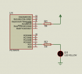
You asked me ? Yes, my project works. I have attached Simulation Video. It will surely work in hardware also. Crystal and associated Capacitors should be added. A 10 uF 6.3V and 100 nF 16V has to be added across PIC power pins and close to PIC on the PCB.
 

dannyf

Joined Sep 13, 2015
2,197
there is nothing in datasheet that different with the other types
Two things make or break a good embedded programmer: programming skills, and your willingness and ability to comprehend the datasheet.

If you aren't willing to read and understand the datasheet, you will have a miserable time in this business.
 

Thread Starter

arashian1

Joined Sep 9, 2016
39
In mikroC PRO PIC "Edit Project" dialog box set Osc type to XT if you are using 4 MHz and HS if you are using more than 4 MHz Crystal.
upload_2016-9-30_13-45-28.png

upload_2016-9-30_13-46-59.png

sbit LCD_RS at RC0_bit;
sbit LCD_EN at RC1_bit;
sbit LCD_D4 at RC2_bit;
sbit LCD_D5 at RC3_bit;
sbit LCD_D6 at RC4_bit;
sbit LCD_D7 at RC5_bit;
sbit LCD_RS_Direction at TRISC0_bit;
sbit LCD_EN_Direction at TRISC1_bit;
sbit LCD_D4_Direction at TRISC2_bit;
sbit LCD_D5_Direction at TRISC3_bit;
sbit LCD_D6_Direction at TRISC4_bit;
sbit LCD_D7_Direction at TRISC5_bit;

void main() {
ANSEL = 0x00;
CMCON = 0x07;
TRISC = 0x00;
LCD_INIT();
LCD_CMD(_lcd_clear);
LCD_CMD(_lcd_cursor_off);

while(1){
LCD_OUT(1,1,"IMAN");

}
}
upload_2016-9-30_13-48-55.png

who knows during programming the programmer message OSCCAL what does mean?
 
Top