PIC Breadboard Adapter

Thread Starter

tracecom

Joined Apr 16, 2010
3,944
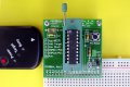
Attached is a photo of an adapter to connect an 8, 14, or 20 pin PIC to a solderless breadboard. As you can see, all I/Os are brought out to the breadboard. In addition, there is a connector for a PICkit 2 or 3. Also note that the power for the PIC can be provided from the breadboard power rails.

Just wanted to show it to the group.
 

Attachments

DerStrom8

Joined Feb 20, 2011
2,390
I designed and built something very similar, though it has a PIC18F1220 permanently soldered to it. I designed it to be about the size of a 40-pin DIP so that it can easily fit on a breadboard. Unfortunately I don't have any photos of the real thing, but somewhere I have an Eagle3D rendering of it. I'll see if I can find it.

Did you design the board in your OP?
 

Thread Starter

tracecom

Joined Apr 16, 2010
3,944
I designed and built something very similar, though it has a PIC18F1220 permanently soldered to it. I designed it to be about the size of a 40-pin DIP so that it can easily fit on a breadboard. Unfortunately I don't have any photos of the real thing, but somewhere I have an Eagle3D rendering of it. I'll see if I can find it.

Did you design the board in your OP?
Yes, it's my design. I originally laid out three individual boards: one for 8-pin PICs, one for 14-pin, and one for 18-pin. Those efforts gave rise to this idea...a low cost development platform that is quick to set up and easy to use.
 

DerStrom8

Joined Feb 20, 2011
2,390
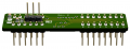
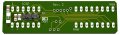
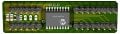
Here are three images (different camera angles) of the rendered PCB. I used Eagle 5.6.3 to design the board, Eagle3d to create a POV file, and Pov-Ray v.3.6 to render it.

AngleView.png
135292_579044208774148_204758954_o.jpg
887343_579044242107478_1088751718_o.jpg

I was planning on doing a Rev. 3 design, but time has not allowed it. Hopefully I will be able to do that sometime in the future.

The above lays out ports A and B in straight lines designed to plug directly into the breadboard. The board has an ICSP header that also plugs into the breadboard. It was supposed to use double-length headers so you could connect the programmer either through a cable to the BB or directly to the board from the top, but the headers that arrived were not extra-long. Since I had them, though, I used them anyway.

The board can be powered from between ~7.5v-9v without having the on-board voltage regulator overheat, and sometimes can be powered from 12v for short periods of time. The jumper at the top connects/disconnects MCLR from V+ (through a diode), so you can select RA5 to be either I/O, or connect it as MCLR to an external switch for resetting the board. I usually just leave the jumper set to connect the MCLR/RA5 pin to V+.
 

DerStrom8

Joined Feb 20, 2011
2,390
The downfall is that mine is limited to the use of only the 1220. I would like to design one that has a universal ZIF socket like yours. I think that would be far more useful!
 

MaxHeadRoom

Joined Jul 18, 2013
30,808
The downfall is that mine is limited to the use of only the 1220. I would like to design one that has a universal ZIF socket like yours.
I originally made a few up using strip board quite successfully, and also there is a handy products by Olimex that you can customize, free P/P from UK.
ebay 270965724893 comes with RS232 and a couple of other simple options.
Max.
 

John P

Joined Oct 14, 2008
2,068
I don't understand the need for this. I put PIC processors on breadboards all the time, but I just plug them in directly. When I bring in the 5-pin in-circuit programmer cable, it happily has 3 pins in the right order to connect to pins 18-20 of the PIC16F690 chips that I use, and a couple of jumpers connect up the other two wires. If I had to use more jumpers, I still wouldn't call it a difficult process.
 

DerStrom8

Joined Feb 20, 2011
2,390
I don't understand the need for this. I put PIC processors on breadboards all the time, but I just plug them in directly. When I bring in the 5-pin in-circuit programmer cable, it happily has 3 pins in the right order to connect to pins 18-20 of the PIC16F690 chips that I use, and a couple of jumpers connect up the other two wires. If I had to use more jumpers, I still wouldn't call it a difficult process.
ICSP and power circuitry tends to take up a lot of extra space on the breadboard, and if you have a small breadboard (or a large circuit), every square inch helps. I designed mine so that it doesn't take up as much room on the BB, as well as making the prototyping board more portable. You don't have to bring a whole mess of components with you if you want to use the PIC on the fly. All you need is the board and a battery and you can run the uC.
 

John P

Joined Oct 14, 2008
2,068
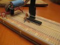
Have it your way, but for the things I do, I don't see the need. Here's the minimum setup for a PIC16F690 and the connection to a PICKIT 2 clone programmer. In fact I just about always add 2 more jumpers to supply Vcc and Gnd to the breadboard's contacts, but this gets the program into the chip.
 

Attachments

DerStrom8

Joined Feb 20, 2011
2,390
As well as the neatness aspect, beginners with PICs may not know how to set up the ICSP or power correctly. Having it fully consolidated on a separate board makes for much quicker prototyping and testing of code.
 

ErnieM

Joined Apr 24, 2011
8,415
This is almost the "buy or build" question we all face: should I spend the time to design, build, debug, and refine some new thing I need, or just go out and buy the nearest equivalent?

Both John P and DerStrom8 make some good points here. When starting off the beginner can use all the hand holding possible. That first embedded project combines building a circuit, writing and compiling some code, connecting a programmer, and observing the results.

And if those results are as exciting as watching a paint dry what does one do? At least paint does *something* (gets less sticky), what if your project just sits there, no LEDs blinking, no "zip" when it moves, no "bop" when it stops, no "whirr" when it stands still?

So when at the starting gate I lean towards DerStrom8's view. With so many variables in an embedded project (circuit design, circuit build, component integrity, code correctness, programmer correctness) to contend with a beginner can use all the assistance possible!

That is why a purchased, assembled, and tested development board with a programmer are on the top of my suggested list. They sit there on my list along with a set of lesson plans for the board. Such a board, as minimum, needs an inexpensive push button, some LEDs, and a potentiometer. That will teach you the basic operations of inputting digital (the button) or analog (the pot) signals, and making some digital output observed on the LEDs.

Now you have some very useful tools that together eliminate the variables of the design, the build, and the programmer, and you can concentrate on the code until it works.

It may be useful to also provide some general connections for "expansion," some way to use the board once the lessons are complete. I've used these boards as a starting point for a few projects when I just need a micro and little else. Heck, for a few years I even used my PICkit ONE as an ICSP programmer by adding some jumpers to daughter boards.

When I do need anything beyond that beginners board John P's comments make more sense. While I don't use solderless breadboards I have until the last couple of years used the Radio Shack soldered breadboards that mimic the same pin pattern. PICs are obtained in DIP packages and centered directly on the lands. ICSP goes into a corner taking up very little room. Come out neat and proper, but it's no where near my first trip around the block.

With breadboards I never had the need to convert a DIP package to another DIP package.

Lately I've changed to using mostly SMD parts for bread boarding. While 0805 resistors can fit on those RS boards you can pull the lands way too easily, so I now use inexpensive bread boards I get from China. These are just a sea of plated thru holes on 0.1" centers. They also look much nicer!

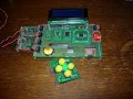
I do use adapter boards all the time to change SOIC and QFN to 0.1" patterns. My development boards tend to look like this (partially disassembled) prototype:


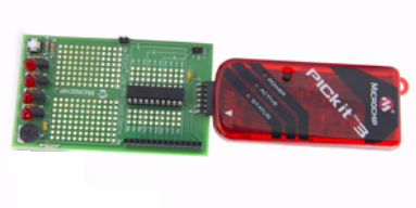
My choice for starter board:
PICkit 3 Low Pin Count Demo Board


Attachments

Top