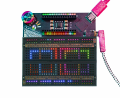
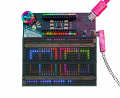
At first glance, it looks pretty impressive. It looks like it has a programmable analog switch between all adjacent holes that you can enable by using the probe to essentially draw in jumpers wherever you want.
Presumably they cannot cross, so I would guess you need jumpers for that. And there is undoubtedly some resistance inserted and a current limitation.
I would want a hands-on trial by myself or someone I trusted before buying.
it is using analog switches to make connections. max current per switch is 15mA, max current per chip is 100mA. also the analog switches (CH446Q) are supplied by +/-9V so any potential that this handles must fall inside those bounds. it is a showroom piece but imho completely useless limited.
Well they do look impressive but what has been echoed on here is that hands on trial part. maybe if they sold small versions of this to trial the tech then order the bigger ones if the small ones fit the bill. Standing on the outside and lacking the hands on part they do look impressive and a huge time saver assuming they work as advertised.
They can cross, any connection can connect to anywhere else, including a bunch of internal nodes for measurement or routable GPIO or power supplies. There's some theoretical limits but they're pretty hard to hit, the routing algorithm can usually find a path even if that means making some intermediate hops.
Here's the schematic, you can kinda trace through how a connection gets from one place to another if you stare at it long enough.
There's not really a current limit, just a voltage limit + crossbar resistance, so 9V / ~45Ω = 200mA. Or if you were somehow dropping +9V to -9V you can push 400mA, it doesn't break them, I've tried it.
It fills the unused routing space on the board with parallel connections to get lower resistance connections, so that current gets spread out across a few chips. Those CH446Qs can handle more current than they claim.
And that's also kinda handled with policy because I didn't want people being scared to use it.
Well they do look impressive but what has been echoed on here is that hands on trial part. maybe if they sold small versions of this to trial the tech then order the bigger ones if the small ones fit the bill. Standing on the outside and lacking the hands on part they do look impressive and a huge time saver assuming they work as advertised.
That's actually a good idea. There's no smaller one (well, the V1 / OG, but it's much worse), but I should just add an option to order them with a return label already in the box. Until I add that officially, if you put that in the order notes, I'll do it. Just order from me directly because Mouser will make that a nightmare.
Hey! I'm the guy who makes these (thanks, Google alerts.) I'm happy to answer any questions you have about it.
They can cross, any connection can connect to anywhere else, including a bunch of internal nodes for measurement or routable GPIO or power supplies. There's some theoretical limits but they're pretty hard to hit, the routing algorithm can usually find a path even if that means making some intermediate hops.
Here's the schematic, you can kinda trace through how a connection gets from one place to another if you stare at it long enough.
There's not really a current limit, just a voltage limit + crossbar resistance, so 9V / ~45Ω = 200mA. Or if you were somehow dropping +9V to -9V you can push 400mA, it doesn't break them, I've tried it.
It fills the unused routing space on the board with parallel connections to get lower resistance connections, so that current gets spread out across a few chips. Those CH446Qs can handle more current than they claim.
And that's also kinda handled with policy because I didn't want people being scared to use it.
Well now about the small boards at a reasonable price for us to look into and allow us to play, the thing we all love to do. This would cement your tech and your place in the breadboard choices. Next would be how big a breadboard can you get and the thing no one likes to ask but I love it is. How much, are you able to compete with breadboard choices out there now. Jumpers or not. Or can you at least justify the extra cost into a time saving formula. this is what matters to me and I'm sure others also.
Well now about the small boards at a reasonable price for us to look into and allow us to play, the thing we all love to do. This would cement your tech and your place in the breadboard choices.
The realities of low-ish volume electronics manufacturing would mean an even smaller 1/4 size Jumperless would still be like ~80% of the cost, and be pretty useless. As for making larger ones, the cost would go up faster than just simple 2x cost for 2x breadboard area for a bunch of reasons. The more efficient way is to just get 2 and connect the the Nano headers together and route stuff through them.
How much, are you able to compete with breadboard choices out there now. Jumpers or not. Or can you at least justify the extra cost into a time saving formula. this is what matters to me and I'm sure others also.
Well, it's not really meant to compete with a $6 breadboard or those 3M things where they bolt a couple breadboards to a piece of plexiglass and charge absolutely ridiculous prices. It's more a weird electronics multitool in a breadboard form factor, because that's the de facto standard things fit into.
I don't know what your time is worth or what your workflow looks like, but I use them all the time and find it pretty handy. But no, it would be hard to justify mathematically against regular breadboards. It's still a bit of a boutique item and hopefully someone starts cranking them out in China for super cheap (it's open source and I really want someone to do this, no takers so far.)
The realities of low-ish volume electronics manufacturing would mean an even smaller 1/4 size Jumperless would still be like ~80% of the cost, and be pretty useless. As for making larger ones, the cost would go up faster than just simple 2x cost for 2x breadboard area for a bunch of reasons. The more efficient way is to just get 2 and connect the the Nano headers together and route stuff through them.
Well, it's not really meant to compete with a $6 breadboard or those 3M things where they bolt a couple breadboards to a piece of plexiglass and charge absolutely ridiculous prices. It's more a weird electronics multitool in a breadboard form factor, because that's the de facto standard things fit into.
I don't know what your time is worth or what your workflow looks like, but I use them all the time and find it pretty handy. But no, it would be hard to justify mathematically against regular breadboards. It's still a bit of a boutique item and hopefully someone starts cranking them out in China for super cheap (it's open source and I really want someone to do this, no takers so far.)
What kind of bandwidth do the connections offer? is there any degree of crosstalk (like capacitive) between distinct connection? do you have the ability to generate a PCB design from a connection netlist?
I guess I'm asking what limitations to signal flow are there compared to say a 3" piece of copper wire.
I think its a very neat idea, unlike physical breadboard, connections can change in real-time, to achieve that on an ordinary breadboard requires actual circuit logic, so it can in some ways, simulate logic design.
There's not really a current limit, just a voltage limit + crossbar resistance, so 9V / ~45Ω = 200mA. Or if you were somehow dropping +9V to -9V you can push 400mA, it doesn't break them, I've tried it.
i appreciate feedback that they will not blow up. this is not what i expected..
so kudos on the design and making it open source (i was impressed with documentation and instructions)
The TL;DR is just the physical breadboard puts the 3dB roll-off at ~13MHz, and a signal passing through the crossbar matrix brings it down to around ~8MHz.
It makes sense these are pretty high, these CH446Qs were originally made for switching video signals so bandwidth was pretty important when they were designing them. Keep in mind this isn't a hard limit, it's just where the signal gets attenuated by the (arbitrarilyish) defined 3dB, so your signal's amplitude is reduced by √2.
Isolation is -84dB for unconnected rows, but really a lot of this just comes down to the fact that a breadboard is basically a bunch of crappy capacitors.
It's also an easy thing just test on the board, the PWM on an RP2350 goes up to 62MHz, so you can just connect an oscilloscope to any row (15 in this case) and do
If you're in the universe of worrying about how many inches of wire your signal is going through, a breadboard (Jumperless or not) is gonna be complete garbage. But like 12.5MHz SPI or USB or any signal you'd typically see on a breadboard gets through just fine, I haven't tested the crazy fast things like LVDS or HDMI but I'd be super interested for someone to try it and let me know.
I think its a very neat idea, unlike physical breadboard, connections can change in real-time, to achieve that on an ordinary breadboard requires actual circuit logic, so it can in some ways, simulate logic design.
Yeah that's where it really gets interesting. It has a whole-ass MicroPython interpreter onboard so you can just put down the parts you're interested in and then have the Jumperless set the clock and address bits for example. Or have it read the state of your circuit at different times and store it in a file.
There's kind of an endless rabbit hole of things you can do when wiring itself can be scripted. And to preempt a future question, it takes about 1.5 us to make any given connection (with micropython's overhead it takes longer but there's a few ways around it.)
I only bothered to think about switching speed because there's a user messing with using the Jumperless to do switched resistors and capacitors for audio circuits.
I could do that, but I never will on principle. Any auto generated PCB looks like complete garbage, there just isn't the information in a netlist to do that well. And laying out PCBs is the fun part. But yeah you can export the netlist in a variety of formats and do whatever you want with them, I just don't want to encourage that particular style of laziness in EE. Not to be a snob, I just think it costs beginners way more time than it saves in the long run.
I usually tell people in my Discord that if they want to make a PCB of anything and don't know how, I will personally walk them through it step-by-step (or just do it for them really quick and explain what I did and how.)
i appreciate feedback that they will not blow up. this is not what i expected..
so kudos on the design and making it open source (i was impressed with documentation and instructions)
It still trips me out that this works, but turns out putting 220Ω resistors in series with the Vdd and Vee lines of the crossbars helps a ton. Not that they'll never blow up, it still happens in weird situations. But it takes like 10 seconds to replace those QFPs with a hot air gun. If people are worried or know they'll be pushing limits, they can ask for a bag of spare CH446Qs in the box.
btw don't take any of this as me trying to sell Jumperlesses, please don't buy one unless you want to, it's just fun answering questions from a more technical crowd.
Certainly this is an interesting concept, and a novel product! BUT when I use a breadboard of this shape I want to see every connection, to verify that it is really what I wanted.
So I will not be ordering a set of them. But for a few applications it could be a good choice.
Oh yeah I totally agree, this thing would be so useless without visual feedback like that. Which is why I went through the trouble of having custom breadboard clips made with a cutout for an RGB under every hole. It assigns a unique color to every net and draws a little wire between them. And if they're hooked up to a GPIO, ADC, DAC, or current sensor they'll color the net based on the live voltage (and little marching ants for current.)
The Jumperless V5 is basically a programmable breadboard that lets you create and change circuit connections through software instead of manually moving jumper wires. It looks like a really interesting tool for quick prototyping, testing ideas, and experimenting with electronics.
The biggest advantage seems to be the ability to modify circuits quickly without constantly rewiring everything. It could be very useful for Arduino, microcontroller, sensor, and small electronics projects. However, for simple circuits, a regular breadboard and jumper wires may still be the easier and more affordable option.
It’s a unique concept though almost like having a breadboard that can wire itself.
The Jumperless V5 is basically a programmable breadboard that lets you create and change circuit connections through software instead of manually moving jumper wires. It looks like a really interesting tool for quick prototyping, testing ideas, and experimenting with electronics.
The biggest advantage seems to be the ability to modify circuits quickly without constantly rewiring everything. It could be very useful for Arduino, microcontroller, sensor, and small electronics projects. However, for simple circuits, a regular breadboard and jumper wires may still be the easier and more affordable option.
It’s a unique concept though almost like having a breadboard that can wire itself.
It strikes me as ideal for schools, colleges - perhaps he can get some big contract, make some serious dosh! The only unattractive aspect of the device is that it needs a PC or something on which to define the wiring layout, but it does give you a lot in return.
Incidentally @Kevin Cappuccio - does it provide sanity checks? prevent short circuits or pointless wiring (wires that connect places to themselves) etc?
That’s a good point. A tool like this could be really useful in schools and colleges, especially for electronics, engineering, and STEM programs where students need hands-on experience. If it gains enough attention and proves reliable, educational institutions could definitely be a strong market and potentially lead to some larger contracts. It’s an interesting idea with a lot of potential.
That’s a good point. A tool like this could be really useful in schools and colleges, especially for electronics, engineering, and STEM programs where students need hands-on experience. If it gains enough attention and proves reliable, educational institutions could definitely be a strong market and potentially lead to some larger contracts. It’s an interesting idea with a lot of potential.
I also wonder if it could acquire a knowledge of various devices, so if I wanted to wire up some chip, it can see that I'm short circuiting an output maybe or leaving an input floating and so on...
In fact that is a potential subscription service, where one gets access to that online device database for a small fee, you need a computer anyway to define the wiring...
That’s a good point. A tool like this could be really useful in schools and colleges, especially for electronics, engineering, and STEM programs where students need hands-on experience. If it gains enough attention and proves reliable, educational institutions could definitely be a strong market and potentially lead to some larger contracts. It’s an interesting idea with a lot of potential.
I see the issue that using a computer opperated breadboard will certainly reduce any hands-on experience! An adequate simulator would be a more efficient experimenting device, as I see it. SO the simulator will really need to be able to ask questions prior to starting the simulation. The closest that I have seen are the PCB layout software design rule checks.
IN ADDITION, I have had to work with some recent engineering graduates who have not had enough actual REAL WORLD experience with details like properly making actual connections with real wires and real components.
Incidentally @Kevin Cappuccio - does it provide sanity checks? prevent short circuits or pointless wiring (wires that connect places to themselves) etc?
Yep, it does that. How it works internally is every node has a set of other "do not intersects" where it will just ignore connections to those, so connect(TOP_RAIL, GND) is just a no op (there's a debug flag to tell you if you want.) Of course you could get around it by putting a jumper on the board and connecting either end, unless you took the time to set custom do not intersects on either end.
The only unattractive aspect of the device is that it needs a PC or something on which to define the wiring layout, but it does give you a lot in return.
Man, this is so helpful for figuring out what my docs are unclear on. The prime directive of V5 was to make it perfectly useable without a computer, you can do everything with the probe and clickwheel and just plug it in for power. The JumperlOS firmware is so sprawling at this point that it basically is its own computer.
Just a fun hack that it does, it can sense the difference between floating and grounded on its GPIO by twiddling pullups. There is some old code for knowing about chips, but now that the python stuff is mature, I figured it's better for users to put that in a script so it's not making any assumptions the user is unaware of. But just having a visual pinout guide might be really cool.

 Facebook
 Google
 GitHub
 Linkedin